|
|
|
|
|
|
Measuring controlled impedances on short traces in a manufacturing environment
Application Note AP127
|
|
Background TDR (Time Domain Reflectrometry) has become the established technique for the measurement of controlled impedances on printed circuit boards. Ideally, trace lengths of approximately 6 inches (as recommended in Standard IPC2141) allow for easy measurement, as there will be a significantly flat region of the trace allowing an accurate average impedance measurement to be made. The measurement range is chosen to avoid the start and end of the trace, as these areas are not flat owing to TDR measurement characteristics.
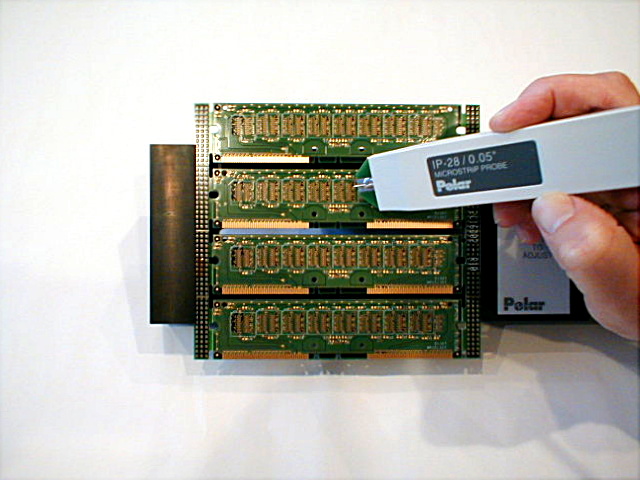
The diagram shows the impedance waveform for a 7 inch 28 ohm trace. Problems when measuring a short 28 ohm trace TDR measuring systems and their cables have an impedance of 50 ohms. When making a measurement, time (or distance) is needed for the impedance waveform to change from the 50 ohm cable output to the impedance of the trace. In the diagram, the transition from 50 ohms to 28 ohms occupies the first 2 inches of the trace. If the TDR has a fast risetime (e.g. 35pS), there will typically be severe "ringing" where the probe/cable connects to the trace and measurement cannot be made until this has settled. Typically the user will apply a filter to minimise the ringing, however this has the effect of reducing the pulse risetime (e.g. to 200pS). A solution If the launch impedance value and the trace impedance are very close, then minimal time is required for the trace impedance to reach its actual value. To achieve this, Polar produces an IP28 Impedance Matching Probe (e.g. 28 ohms for Rambus®) to make the connection to the trace under test and is used in conjunction with the CITS measurement systems. The small discontinuity between the 28 ohm probe output and the trace under test (nominal value of 28 ohms) is likely to be under 2 to 3 ohms, allowing the measurement region to begin close to the trace start. It should be noted that the IP28 matching probe is effective and accurate for measuring impedances that are 28 ohms ±10%. The net effect of the above is that a fast risetime pulse causes ringing and a slower risetime pulse needs time to reach a stable value. Hence the first 1 to 2 inches of the trace are unlikely to be suitable for a stable reading of impedance. Where the 28 ohm trace (e.g. Rambus®) is only 1 or 2 inches in length, how can the value be measured? The matching probe is connected to the test trace using conventional sprung test probes (pins) that extend from the edge of the probe body. If you are probing manually, you obtain optimum matching by holding the probe vertically and ensuring that the sprung pins are fully depressed. More consistent results are obtained when using a Robotic Impedance Test System that will automatically probe perpendicular to the PCB under test and apply a repeatable and consistent probing pressure. Manual results are further enhanced when there is a 50mil (0.05") pitch between the trace signal and ground rather than 100mil.
Selecting the measurement area To obtain repeatable and consistent results in manufacturing, you need to select a flat test region that starts after any discontinuity near the trace start and ends before the impedance begins its climb towards an open circuit at the trace end. Although some publications may recommend the specific area to be tested (e.g. 50% to 70%) this is not always optimum for short traces. We suggest that you select the test region by choosing the most flat undisturbed interval that falls between any aberrations near the trace start and the climb towards an open circuit at the trace end. Once selected, the same range should be used for all subsequent tests of that type of PCB. Typical results The results below are for two short traces of a nominal 28 ohm stripline using a handheld IP28 ohm matching probe and indicate that with care, you are able to obtain satisfactory results down to 1 inch.
2 inch trace
1 inch trace |