|
|
|
|
|
|
Unbalanced PCB Tracks and Differential Impedance
Application Note AP143
|
|
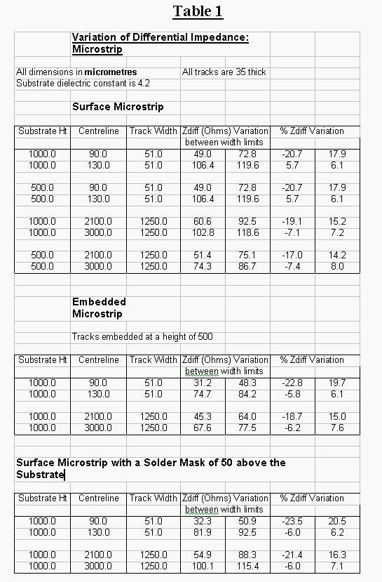
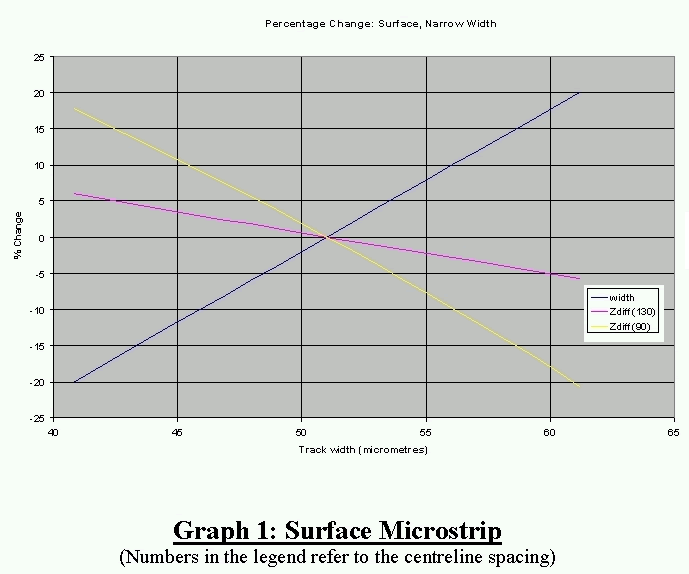
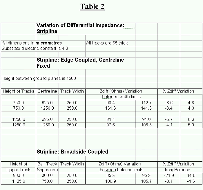
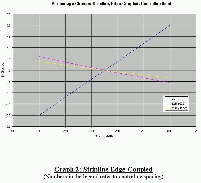
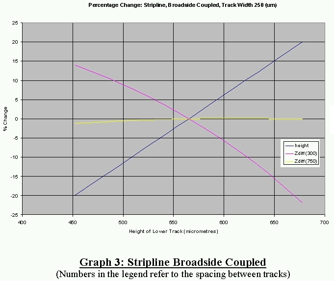
Introduction Normally to obtain a particular value of differential impedance, the two signal tracks are assumed to have the same cross-section. This is the balanced track case. This case is the one used in most impedance calculation software. However, due to manufacturing techniques and tolerances, the two tracks may have different cross-sections. This is the unbalanced track case. This note discusses the effect of track unbalance on the value of the differential impedance. The calculation of the differential impedance of unbalanced tracks is more complicated than the calculation of the impedance of balanced tracks because geometrical and electrical symmetry cannot be used. Using the same calculation method as that used in Polar's products, the capacitance and inductance matrices of the two tracks was calculated. From these matrices the differential impedance can be determined. Results Results are presented for edge-coupled microstrip and stripline. Typical values of the extreme practical widths of track are used. Taking the balanced case as reference, the width of the right-hand of the pair of tracks is varied up to ±20%, but maintaining the same centreline position. In the tables below, the centreline value is the distance between the left-hand edge of the left-hand track and the centreline of the right-hand track Broadside-coupled stripline is also considered. In this case identical tracks are balanced about the centreline between the ground planes. The lower of the two signal tracks is varied by ± 20% up and down about its balanced position. Microstrip Table 1 shows the results at a ± 20% variation of track width, for various configurations of microstrip. Graph 1 shows the percentage changes in track width and differential impedance, for surface microstrip, for a substrate height of 1000mm and fixed centreline spacings of 90mm and 130mm. That is, Graph 1 is for the data in the first two rows of Table 1. Similar graphical variations apply to the other pairs of data in Table 1. In general the higher the differential impedance, the smaller the percentage change in the impedance. Thus, impedances greater than 100 Ohms only change by approximately ± 7%. For impedances less than 100 Ohms, the change increases as the impedance for the balanced position decreases. The amount of change also depends on the separation between tracks. Thus at a centreline spacing of 90um and a balanced track width of 51mm, the separation is 13.5mm and an impedance of 61.7 Ohms. Then the change is – 20.7% to 17.0%. Whereas at a centreline spacing of 2100 mm and a balanced track width of 1250 mm, the separation is 225mm and the impedance is 80.3 Ohms .The impedance change is – 19.1% to 15.2%. This pattern is repeated for both the embedded and the surface microstrip cases. Stripline Table 2 shows the variation of differential impedance for a ± 20 % variation in the width of one track for edge-coupled tracks and a ± 20% variation in the position of the lower track of broadside-coupled tracks. For edge-coupled tracks, the variation of differential impedance is similar to the edge-couple microstrip case for similar impedances. Thus there is a greater variation for low impedance where the tracks have a lower separation than for high impedance where the tracks have a wider separation. Graph 2 shows an example. Graph 3 shows the variation of differential impedance for broadside-coupled tracks. For a track spacing equal to half the ground plane spacing, the change in impedance is almost constant for a ± 20% variation in the track height. This small change also occurs for other track widths and ground spacings. When the tracks are not approximately separated by half the ground spacing, much greater changes in the differential impedance occurs – see Graph 3.
|