|
|
|
|
|
|
Modeling a Broadside Coupled Differential Pair without Ground
Application Note AP147
|
|
Modelling structures No matter how many structures we include in the Si8000 it seems that we never have enough! If we don’t model the particular structure that you need, here is a trick that may help you to work around the problem and calculate good, accurate values. Using virtual grounds Consider the following broadside coupled differential structure...
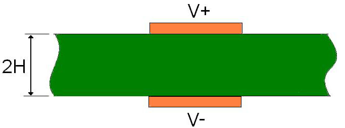
Figure 1 When the tracks are driven in equal but opposite sense, the potential at every point equidistant from the two is always 0V (half way between +V and –V). We can use this to our advantage because those points form a virtual ground plane that lies exactly equidistant from each track. This virtual ground plane is shown in Figure 2 below.
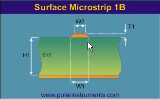
Figure 2 The Si8000 does not have a structure exactly like this, but it does have the Surface Microstrip structure shown in Figure 3 below which is exactly half of it.
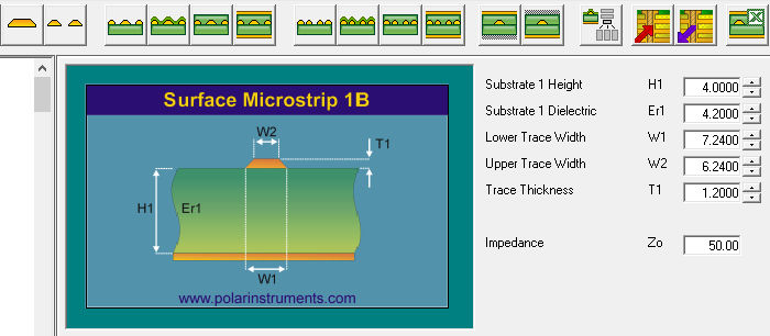
Figure 3 The track in Figure 3 corresponds to the upper track in Figure 2, and the planes correspond. By turning Figure 3 upside down, it corresponds to the lower track in Figure 2. Notice the significance of height H in the three figures. The impedance of the differential pair in Figure 1 is the same as their impedance in figure 2, which in turn will be twice the impedance of the surface microstrip in Figure 3. (Because in Figure 1 (and Figure 2) both signal tracks are driven, one by +V and the other by –V. So the driving voltage = +V-(-V) = 2V which is double that in Figure 3. However, the current will be the same and therefore the impedance is double.) So, to calculate the differential impedance of Figure 1, simply calculate the impedance of Figure 3, and double it. The Si8000 Quick Solver is convenient to use for this purpose, as shown in Figure 4.
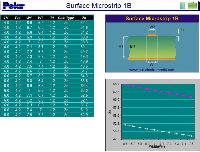
Figure 4 The impedance of the surface microstrip shown is 50 ohms, so the impedance of the broadside coupled differential pair will be twice 50 ohms = 100 ohms. Remember the H relationship. Conclusions Look for virtual ground planes between differential tracks to see if a single ended model with ground can be adapted to fit your needs. The virtual ground is a tool, and it may not always be immediately apparent that it exists between two conductors driven differentially. Look beyond the obvious to see if this tool can be adapted to suit your different and individual needs and use it to your advantage. Note the flexibility of the Si8000 Quick Solver in adapting to the different measurement units. It can even accept mixed units for a calculation; for example, some dimensions may be entered in mils, the rest in microns. If you have purchased the Si Excel Interface option you will note also how the Excel table and chart (below) can convey a helpful quantitative and graphicimpression of what is happening to impedance as the structure dimensions vary.
Here the Polar Si8000 Excel Interface models the surface microstrip structure, showing how impedance varies with track width and with laminate thickness. This simple relationship is intuitive for single-ended structures, but for differential and coplanar structures it is complex and impossible to predict without a graphic calculator such as this. Custom Excel sheets to suit your specific work and objectives can be built in minutes. Please contact your local Polar office about this or any other impedance questions |