|
|
|
|
|
|
Using coarse and fine goal seeking convergence on the Si8000m and Si9000e field solvers
Application Note AP170
|
|||
|
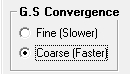
Goal seeking parameters on controlled impedance structures The Si8000m and Si9000e field solvers "goal seek" for parameter dimensions (core thickness H1, trace widths W1, W2, etc.) on controlled impedance structures using an iterative calculation process. Goal seeking continues until the convergence process brings the parameter within acceptable limits. Controlled impedance structure parameters Although any parameter can vary, many parameters within a structure will be fixed and will not require goal seeking. Some parameters will be governed by the materials purchased. For example, the trace thickness T1 will be determined by the weight of the copper chosen (although on outer layers the trace may be plated up above the original thickness after etching.) The substrate dielectric Er1 will be a function of the glass/resin mix (assuming FR4) and will be in the order of 3.8 to 5.0 (bulk values) though should only vary within small limits of the specified value between batches. The coating dielectric constant CEr will be a function of the coating ink; this example assumes the same Er values for core material and coating. Other parameters will be determined by the manufacturing process: the coating thicknesses C1 and C2 will be a function of the method of application of LPI, curtain coat, spray, etc., the etch factor of the signal trace will be fixed by the etching process. Using coarse and fine convergence Some parameters will be variable but constrained within limits; for example, core thickness will vary but in discrete increments. For these parameters, it is appropriate to goal seek using coarse goal seeking convergence (G.S.Convergence) with its associated time savings to arrive at a final value.
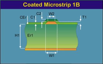
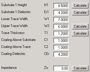
Other parameters, however, such as trace widths W1, W2 and trace separation S1 can be regarded as infinitely variable. For these, to arrive at the correct values within fine limits use fine convergence. Solving for parameter values Consider the Coated Microstrip 1B structure, a coated microstrip with a single dielectric below the single trace The Coated Microstrip 1B model is shown below alongside the default Si8000m parameters for the structure.
Coated Microstrip with single dielectric below the trace
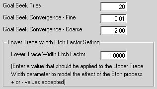
This example describes deriving the parameter values to produce an impedance of 75 ohms. Ensure the Interface Style is set to Standard. (This saves excessive time goal seeking on tolerances — only turn the extended interface on when you have found your nominal values) This is especially true on the more complex coplanar structures, which make extensive demands on your PC. Begin by entering the parameter values which are defined by the supplied materials and manufacturing processes. For this example leave all values as above. Click the Calculate button to calculate Zo.The resulting impedance should be 71.12 ohms. A value as close to 75 ohms as practicable is required. Solving for Substrate height First, goal seek for a value for core thickness to match the thickness produced by the material supplier. Because the value of H1 is not infinitely variable it's appropriate to choose coarse convergence. This will reduce the number of iterations before the value for core thickness (H1) is brought within acceptable limits. Use the Si8000m Configure command to specify calculation parameters.
Si8000m configuration screen By default the number of Goal Seek Tries is set to 20, the value for fine convergence is set to 0.01 ohms and the value for coarse convergence is set to 2 ohms. Change these values to limits appropriate to the application. The etch factor (the difference between W1 and W2) is set by default to 1mil. Alter the value (the Si8000m will model positive or negative slopes) to match the finished process value. To goal seek for height enter a value of 75 ohms in the Impedance text box and click the Substrate 1 Height Calculate button to solve for H1. The resulting value of H1 should be 9.55 mils. In this application the nearest available finished material thickness is 9.3 mils. Calculating for Zo using this value for H1 yields an impedance value of 74.11 ohms, an error of just over 1%. For many applications this would be acceptable Solving for trace width With the dielectric height decided, solve for trace width to produce a final impedance of exactly 75 ohms. Because the trace width is infinitely variable, it's appropriate to use fine convergence. Switch the Si8000m G.S. Convergence setting to Fine. Enter 9.3 mils in the Substrate 1 Height text box, re-enter 75 ohms in the Impedance text box and click the Upper Trace Width Calculate button W2, the upper trace width resolves to 5.78 mils; with the lower trace width etch factor at 1 mil the lower trace width will therefore be 6.78 mil. The resulting impedance will resolve to 75 ohms. |
|||