The Si9000 incorporates fast and accurate frequency-dependent PCB transmission line modelling, and extracts full transmission line parameters across its range of controlled inmpedance structures.
The Si9000 uses Boundary Element Method field solving to extract SPICE RLGC matrices and 2-Port S-Parameters for single-ended models or 4-Port S-Parameters for differential structures and provides high speed plotting of transmission line information for the structure under design.
The designer can choose graphing against frequency for impedance magnitude, loss (conductor loss, dielectric loss and insertion loss), inductance, capacitance, resistance, conductance and skin depth.
Click the Frequency Dependent Calculation tab; the Frequency-dependent interface is displayed.
![]()
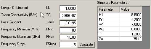
Enter the frequency-dependent calculation parameters, loss tangent, minimum and maximum frequency, frequency steps, etc. and click Calculate.
Click the Graph tab and select the data series from the Display Series dropdown. The Si9000 displays results over the specified frequency range.
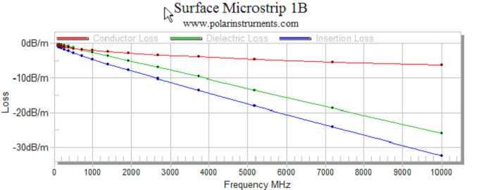
The graph below (All Losses) charts conduction loss, dielectric loss and insertion loss from 100MHz to 10GHz for a surface microstrip structure with the specified parameters.
To change the structure parameters, switch to lossless mode and modify values as required.
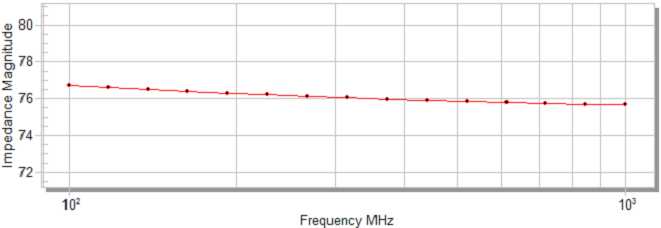
Select other data series and change parameters as required; the graph below shows the variation in impedance magnitude between 100Mhz and 1GHz
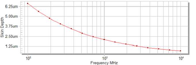
The graph below show the variation in skin depth between 100MHz and 10 GHz.