|
|
|
Solve hard to find PCB faults by comparing device impedances using nodal impedance analysis
Using nodal impedance analysis you can troubleshoot those hard to locate PCB faults down to component level — without having detailed circuit knowledge, without applying power — and without documentation.
If your job entails pcb test or troubleshooting you'll have used a wide variety of equipment and techniques to locate faults. Sometimes faults are just too time-consuming to locate and you'll have simply discarded some PCBs as "uneconomical to repair". Conventional test equipment such as logic analysers and oscilloscopes can only be used on powered boards and requires skill and circuit knowledge - and would still be unlikely to uncover, say, a zener diode with a soft knee. This sort of problem, though, can be easily uncovered by probing a circuit node and displaying its dynamic impedance.
Impedance signatures
If a potential difference is applied across a conductor the resultant current will depend on the voltage applied across the conductor and its electrical characteristics. This voltage-current plot (the dynamic impedance of the component) is distinct for each component and can quickly identify the type (and soundness) of a component. For this reason the V/I characteristics are often referred to as impedance signatures. Fault finding by inspecting or comparing impedance signatures is known as nodal impedance.
Locating faults with nodal impedance analysis
Polar Fault Locators are designed to graphically display the impedance signature of a device. Using nodal impedance analysis pcbs are always tested with no power applied so nodal impedance analysisis inherently safe - and components cannot be damaged. The Fault Locator applies a small sinusoidal voltage across the component and the resulting voltage-current graph is displayed as an x-y plot on a CRT or PC screen. In many cases fault finding is reduced to simple pattern recognition.
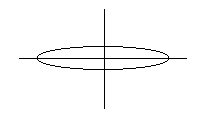
For example the signature for a pure resistance is a straight line, so a change of slope from that of a device on a known good board indicates an obvious wrong value resistance. A capacitor exhibits an elliptical signature whose shape depends on the value of the capacitor.
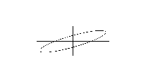
A wrong value capacitance would alter the roundness of the ellipse, leakage would cause the ellipse to appear tilted - both elusive faults, but easily detected using nodal impedance analysis.
Comparison techniques
The most effective method of trouble-shooting will be to simultaneously display good and faulty signatures where good boards are available. Some Fault Locators allow you to "learn" a set of PCB's signatures and send them to service centres - you can even store signatures for components from each of your device vendors.
Testing
digital devices with nodal impedance analysis
Even when you test a digital IC using nodal impedance analysis you are
actually displaying the analog behaviour of the input
protection circuitry. Many failures in digital devices in
service are due to damage in the input/output region of
the device (e.g. caused by lightning strikes, etc. in
telecommunication equipment).
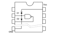
Damage to the I/O region of a digital device will be easily revealed using nodal impedance analysis. Consider the typical digital ic input protection circuit shown below.
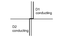
The positive and negative excursions of the Fault Locator drive voltage will cause both diodes to conduct so the signature will appear as below.
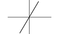
Suppose a large transient severely damages the protection diodes so that the circuit appears as a simple resistor; the signature is dramatically altered and very easy to see - the device is an obvious candidate for replacement.
Nodal impedance analysis is a widely used fault finding technique, independent of the PCB technology employed. It's safe, simple to use and highly effective. If you have a trouble-shooting technique you would like to share with other Polar fault locator users please email Polar Instruments.