|
|
|
|
|
|
Si8000 field solver models changes of thickness of solder mask between traces
Application Note AP169
|
|
|
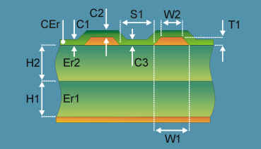
Using the Si8000 field solver to model changes of thickness of LPI solder mask between traces Printed circuit boards are often prototyped at a prototype/quick turn specialist shop before hand over to a volume plant. This note explains how impedance may be affected when the prototype shop and the volume fabricator deploy different soldermask application methods. The Polar Instruments Si8000 Field Solver can be use to predict changes in the final impedance value of LPI coated differential traces due to non-uniform coating thickness (particularly between finely separated differential traces). Some of the most popular application methods for Liquid Photoimageable Soldermask (LPI) are described below; these different methods can result in finished board impedances different from the design value. Silk screen print The silk screen print method applies the LPI to the board with a squeegee blade through a tensioned mesh. Ink deposit is controlled by varying the mesh count and print settings, speed, angle and pressure. Semi-automatic screen print-applied LPISM is the most prevalent solder mask application method today. Non-uniformity of coating can result from the "damming" effect on the leading edge of the trace in the direction of the squeegee movement. There is compression of the screen on the crown of the trace which can result in extremely thin coating(s) and in the case of differential traces, the flooding effect in the space between the traces must be taken into account. All affect the resulting impedance. Curtain-coat With the curtain-coat technique LPI is applied as the printed circuit board passes through a sheet, or curtain, of low viscosity ink falling through a narrow slot. Curtain-coating is widely practised and well understood within the board manufacturing industry. Curtain-coating exhibits a coating variation phenomenon unique to its method – shadowing. Shadowing is the occurrence of reduced solder mask on the trailing edge of traces parallel to the curtain compared with the leading edge of those traces. The trace passing through the curtain presents a dam-like effect causing the build-up of mask on the leading edge of the trace, and reducing the mask on the trailing side of the trace. Electrostatic spray In the electrostatic spray technique LPI is applied from a rotating bell, which, aided by compressed air, atomizes the ink and deposits it on the PCB. The LPI is given a negative charge and the PCB is earthed so the LPI is attracted to the board. However, the electrostatic effect tends to attract the LPI to the copper areas, resulting in less than perfectly uniform coating. Air spray Using air-spray the LPI is applied using single or multiple spray gun(s). The ink is atomized by mixing with decompressing air. Air spray produces generally uniform coating though some users report problems with multiple gun spray systems having a tendency to form "stripes", due to overlap or interference between adjacent guns, across the board. The problems are exacerbated if one technique is used to produce pre-production engineering samples and another to manufacture the final product. The actual differential impedance value of the traces on the finished board can be several ohms different from the design value if the thickness of the LPI coating between the traces changes significantly. In structures such as the edge-coupled coated microstrip below, the final differential impedance value will decrease as the coating thickness C3 increases. Modelling LPI thickness between differential traces The Polar Si8000 allows the designer to calculate impedance changes with
changes in C3. |
|
|
|
|
|
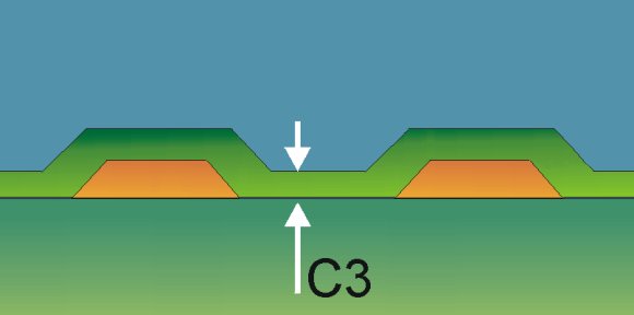
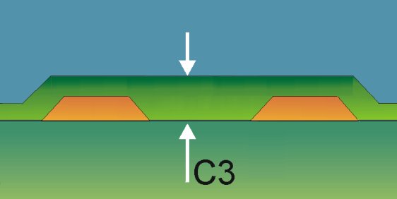
Si8000 models of edge-coupled surface microstrip showing different coating thicknesses between traces. Solder mask thickness between traces is given by C3 in the Si8000 structure diagrams above . Magnified views of the gaps between traces showing different LPI fills are shown below. |
|
|
Minimum fill |
Maximum fill |
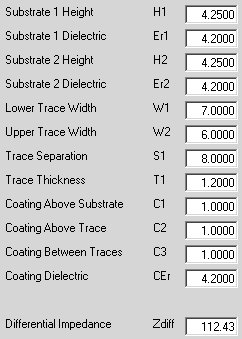
The Si8000 Quick Solver values and solutions for the structures above are shown below |
|
|
|
|
|
Using the parameters above an approximately 3% decrease in differential impedance between minimum and maximum coating thicknesses between traces is observed. The impedance change will depend on the separation between the traces. The Si8000 Excel interface can be used to model the changes in impedance over the above range of parameter values. |
|
The graph above illustrates the change in differential impedance against coating thickness between the traces. |
|