|
|
|
|
|
|
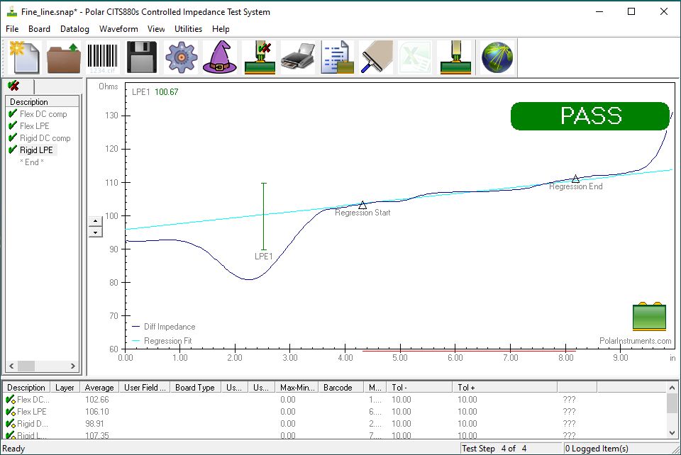
Instantaneous impedance measurement with LPE (Launch Point Extrapolation) applies to fine line traces
Application Note AP8505
|
|
Measuring instantaneous impedance on the CITS880s Thinner copper and finer pcb traces mean that testing impedance controlled PCBs seems to have become more challenging. Historically smooth and horizontal, TDR traces are often now seen exhibiting an upward slope from left to right — the thinner the trace or copper layer, the steeper the slope. Fabricators often ask us, "Where should I measure to get the correct impedance?" The answer is that as the TDR reflection returns to the measurement system, a combination of DC and AC trace resistance adds to the reflection of the instantaneous impedance resulting in an upward sloping trace. The DC resistance shows as a continuing linear rise in the trace. This phenomena is also exhibited in coaxial cables. In order to measure the trace characteristic impedance as predicted by a field solver the DC resistance needs to be removed from the TDR trace. The characteristic impedance calculated with a field solver is the instantaneous impedance, i.e. the impedance at the point of launch into the trace section. Launch point extrapolation applies a regression line fit to a stable sample of the reflection from the trace and projects this regression line back to the launch of the trace – hence Launch Point Extrapolation. This technique requires a TDR with as flat a pulse as possible and, ideally, minimum leading edge perturbations. From 2022 the CITS880s supports an easier to interpret interface for this technique, in addition to conventional impedance measurements for less challenging geometries.
This application note gives first time users some guidelines for setup and the terminologies associated with the technique. It should be stressed that the test limits and time position of the launch point and end point extrapolation are the primary responsibility of the PCB specifier and fabricators should seek their customers' guidance if in any doubt. Normally, then, it would be the board specifier's place to set the LPE1 and the optional LPE2 position and limits. However, here are some "getting started" hints and tips. LPE1 point The launch impedance is the impedance "seen" by the TDR as it first meets the test trace. LPE fits a regression line to the stable portion of the trace to allow the software to "project back" to the impedance at the launch. (The techniqe is needed because the actual TDR trace is altered by abberations as the probe signal transitions into the trace. Aim to set the LPE1 position at the approximate coupon start.* *Hint - test with the probe in the air and then the probe on the coupon to see the end of the probe and start of the coupon.
LPE2 point (optional) The optional LPE2 point is set at an arbitary point – say, 6 inches or further down the line. This second point is in place as a check that the slope is not too steep and there is not more DC resistance in the trace than anticipated. As a guide, you could use the Si8000m/Si9000e Track Resistance Calculator to find the track's DC resistance per inch, then multiply the length to the LPE2 point by the DC resistance and add this figure to the Zo from the Si8000m and set the limit for LPE2 to the Zo plus DC resistance figure ±15%. This will give you a ball park start position. Length... If you are a CITS user you are probably used to seeing the horizontal TDR axis in length units; these will be approximate unless the propagation velocity (Vp) is set correctly in the test editor. The CITS nominally sets Vp to a value somewhere between the stripline and microstrip flight times, a figure which has sufficed until now. For LPE you need to know the resistance per distance so use the latest Si8000m (v14.07 or later) to calculate the Vp per structure and add the correct value to the CITS880s test editor for each test, otherwise, the length displayed in the CITS will not be correct as it needs to know flight time to measure length. Note: Some OEMs may prefer to set the limits for LPE1 and LPE2 in time and in this case the CITS880s editor should be set to display time rather than length. Line fit region ... The CITS880s fits the line to a regression calculation of the data points between the Test From and Test To distances. It is important that, as always, the Test From / Test To points are set on as long a flat portion of the trace as possible. Our guidance to fabricators is that they should seek their customers' advice for LPE1 and LPE2 limits. They should be aware that some people call LPE instantaneous impedance and others may refer to it as a regression fit. All are different ways of saying the same thing. |