|
|
|
|
|
|
Creating accurate and efficient flex-rigid PCB stackups with Speedstack Flex
Application Note AP522
|
|
Speedstack Flex Speedstack Flex allows OEM designers to create accurate and efficient flex-rigid PCB stackups in just a few minutes, with error-free documentation for tighter control over the finished board. For PCB fabricators, Speedstack Flex provides the flexibility to quickly calculate the possible impact of substituting alternative materials to improve manufacturability and reduce cost while maintaining the specified parameters and performance of the board. This note introduces Speedstack's Flex Navigator and briefly walk through the process of adding a flexible core to a pre-built stack up. Adding flexi-cores to a PCB stackup Note: Speedstack Flex is included with Speedstack V10.01 and above; to enable the Flex module you will require a valid Speedstack Flex feature within the license file. Enabling Speedstack Flex To enable Speedstack Flex from within Speedstack select Tools|Options Switch to the Licensing tab and select Speedstack Flex / HDI License (SF)
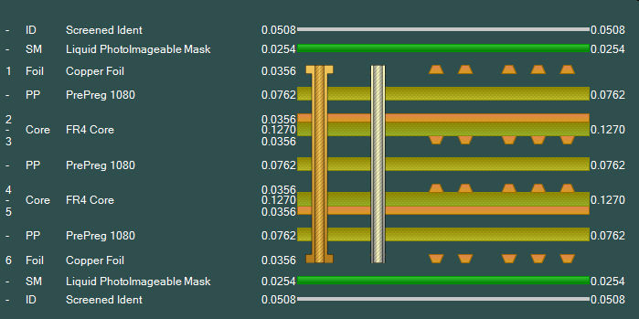
Adding flexible cores From the Speedstack File menu choose Open and navigate to the Samples folder and select 06.mil.stk or 06.mm.stk to load a pre-built 6 layer stack. Edit this stack (below) to add a flexi-core as well as generating a sub-stack with coverlays.
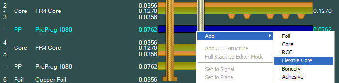
With the stack loaded select the prepreg between layers 3 and 4, right-click and add a flexible core (below.)
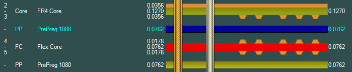
Copy and paste a 1080 prepreg and add copy it above or below the flexible core so no two copper faces are touching. Edit the drills as necessary.
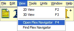
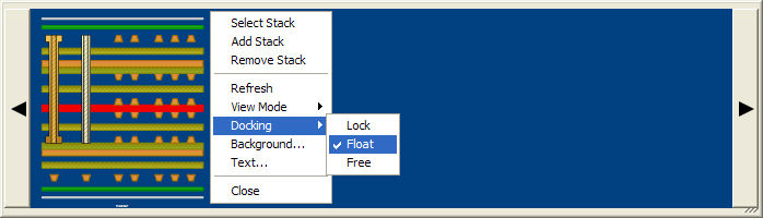
Open the Flex Navigator (F4) under the View option.
In the Navigator, right-click and choose Docking|Float – this will allow the Navigator pane to be resized.
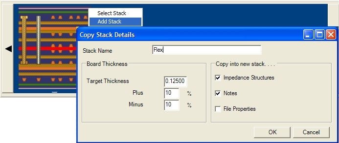
Select the stackup in the Navigator, then right-click the stackup and choose Add Stack; supply the stack details as shown below.
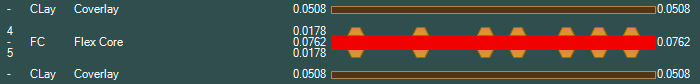
Select Symmetrical Mode and select the new flexible core; in the Stack Editor right click and Add Coverlay – the stack center section should appear as shown below.
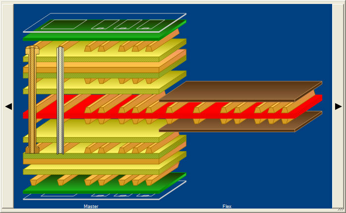
Select the two coverlays and the core (use Ctrl + left mouse click); right click the selected objects and select Flex-Rigid|Disable Material – the materials should disappear from the stack. Click into the Stack Editor window (so that the mouse is not over any part of the stack) – right click and choose Flex-Rigid|Toggle all Material Enables. The disabled materials should reappear.
Click on each stack in the Navigator to select the stack for editing; the selected stack appears in the Stack Editor window and can be edited as normal to add impedances, goal seek, change layer types, add non-copper layers, etc. Note that if extra copper layers are required it will be necessary to remove the sub-stack and remove any impedance structures from the main stack first. |