|
|
|
|
|
|
Atlas Delta-L waveform test settings
Application Note AP9020
|
|||
|
Operational notes for Delta-L waveform test settings The Polar Atlas insertion loss test system incorporates the Delta-L 2 Line and Delta-L 3 Line test methods. All of the acquired TDT Delta L waveforms are used as part of the waveform evaluation so particular care must be taken when choosing waveform test settings if unexpected behaviour is not to be induced. (For Polar users familiar with CITS – this is a significant difference as you may be accustomed to making a choice of the best “test region”.) In particular, the Data Points and Intersample Period (ISP) settings shown below are critical:
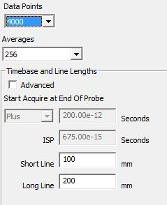
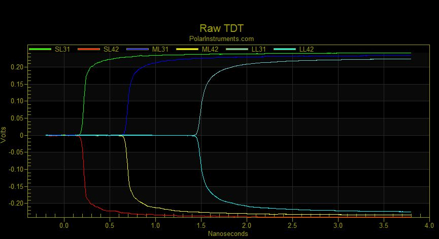
Atlas Test Editor Data Points Data Points – the number of data points in the waveform – simply put, more is better, fewer risks compromising the result. Inter Sample Period ISP – Intersample Period – is the time interval in picoseconds between samples. The Delta-L method appears subject to considerable sensitivity to this setting. It may seem logical to anticipate that as long as sufficient data points are present then the result (S21) should be independent of the intersample period – but that does not seem to be the case. In fact, perturbing the ISP does lead to changes in the S21 reported; no particular investigation has taken place at Polar but there is a possibility that it may be due to the inherent way that the Tek TDR sampler works – this is not a ‘real time’ acquisition system. If it proves absolutely necessary to increase the window width for, for example, 3 Line Delta-L and low Dk materials, then specify 4000 data points and move the ISP up from the factory setting in small increments until satisfied – the intersample period should not be set greater than 1.5pS. Example: In the example below, the Data Points and Intersample Period (ISP) settings shown below lead to questionable results: Settings For the waveform set beow the settings employed were:
The data set shown above is taken directly from one of those sent to the Polar engineering lab. Setting the acquisition start point This is quite complex in operation – essentially it sets the source Raw TDT display ‘window’ that is seen on the screen. Inside the Delta-L processing the start point is quite important as one of the first processes executed normalizes the TDR raw waveforms so that they all start at zero volts. The TDR heads, however, tend to drift somewhat and DC offsets upset the Delta-L math. This compensation is performed in the math by averaging the first ~200 pS (0.2 nanoseconds) of data in each waveform and subtracting the value achieved from each of the data points in the waveform – essentially a DC block shift of the entire waveform. This is why the math with the above waveforms produced questionable results – the Delta-L processing was (prior to Atlas v19.01.17) not based in time but sampled the first 250 samples regardless of ISP – so in this data set above the DC average was taken for the first 250 * 2 pS = 500pS (0.5 nanoseconds) from the waveform display start. Here the display starts at minus 200pS so the DC sampling area is from –200pS to +300pS – clearly taking in some of the short line and then SUBTRACTING this from the remainder of the waveform, resulting in significant error. It is very important that the shortest line ‘transition’ is at least 200pS into the display window. From Atlas v19.01.17, the ISP is taken into account and the first ~200pS is used for the baseline correction rather than the first 250 data points. |
|||