Lossy traces - Where and how to use loss compensation on the CITS
|
||
| Printer Friendly | |
|
Application
Note 156 Lossy traces - Where and how to use loss compensation on the CITS |
|
|
|
| Printer friendly version | |
| Background Polar CITS impedance test systems are easy to set up and use. However care in setting up and understanding the test regions can yield improved measurement accuracy and better R&R. Some fine line traces now exhibit significant loss (a rising trace). Compensation may be applied to correct this on a CITS. First understand what is
displayed |
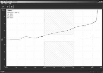
 Impedance test TDR trace of an ideal (lossless) 50 Ohm sample coupon
|
|
Look
now at a lossy trace |
|
|
Hint: Sloping traces may also occur because an etch problem has formed a track which tapers along its length. Before resorting to loss compensation check the trace from both ends. If it slopes up from one end and down from the other you have a tapered trace. If the trace slopes up when measured from either end, this is the result of a combination of loss. |
|
|
---------------------------------------- |
|
|
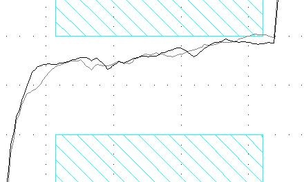
Real Example: Lossy
trace before compensation applied: |
|
|
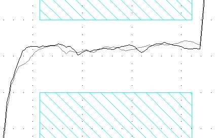
And after: Now you can see the compensation has eliminated the sloping trace. |
|
|
Watch out for: Do not confuse pulse settling time with loss, make sure that the pulse aberrations due to interconnect have settled before you consider that you need loss compensation. On high impedance traces you may need to allow a couple of inches for the pulse to stabilise at its full amplitude before calculating the ohms per inch loss.
|
|
|
Note: Lossy traces
are typically only seen where line width is less than 75 microns (3
mils). You should never need to apply loss compensation on
traces that are wider than 75 microns (unless you are working with
extremely thin foils). |
|
|
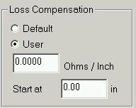
How should loss compensation be applied? Once a figure for the number of ohms per inch of compensation has been agreed with the designer, the next question is "where should the compensation start?" The answer is "At the start of the test coupon trace." The CITS allows you to offset the compensation start position in from the left hand side of the screen. Simply make a test with no coupon and note the position of the end of the test probe. (Typically 1 to 1.5 inches in from the left hand side of the screen). Enter this figure in the "Start at "field.
|
|
|
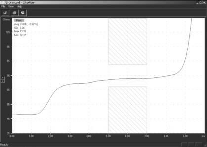
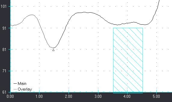
Cits
waveform display highlights compensated |
|
| More
information? Further information on measuring PCB controlled impedances is available by email from richard.smith@polarinstruments.com For information on field solving impedance design software please contact: ken.taylor@polarinstruments.com |
|
|
|
|
Polar Instruments Ltd polarinstruments.com Tel: +44 1481 253081 Fax: +44 1481 252476 © Polar Instruments 2002 |
 |
|
|
|
| © Polar Instruments 2002. Polar Instruments pursues a policy of continuous improvement. The specifications in this document may therefore be changed without notice. All trademarks recognised. | |