|
|
|
|
|
|
Setting CITS880s PASS, INTERMEDIATE and FAIL test limits
Application Note AP8511
|
|
Tolerance The Tolerance parameter of the CITS880s Test Editor defines the tolerance about the nominal impedance to which the track will be tested.
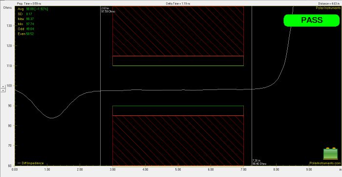
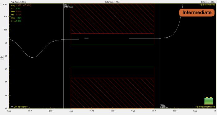
The Waveform Display pane reflects the impedance and distance scales for the test. The graphic above shows upper and lower red cross hatched (FAIL) areas, upper and lower green (INTERMEDIATE) areas and the clear (PASS) area between them, indicating the region over which impedance will be tested. The impedance scale indicates the nominal impedance and PASS, INTERMEDIATE and FAIL impedance ranges. PASS, INTERMEDIATE and FAIL test limits Users have the option of specifying PASS and FAIL impedance limits or, using the Intermediate option shown in the dialog below, PASS, INTERMEDIATE and FAIL impedance limits. The INTERMEDIATE test results provide a guardband between PASS and FAIL. In the example above, the test indicates a PASS if the impedance value remains within the clear area, i.e. falls within ±10% of the nominal impedance over the test area; a reading of between 10% and 15%, defined as the INTERMEDIATE limits, indicates the test should be run again or the result referred for consultation, a reading of greater than ±15% from the nominal impedance is recorded as a FAIL. An INTERMEDIATE result is shown below.
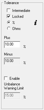
Setting tolerance values Tolerance values are set within the Tolerance section of the Test Editor dialog box.
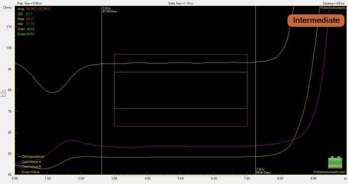
Using locked tolerance values If the Intermediate option is not required, the Plus and Minus tolerances may be locked; i.e. the Plus and Minus settings have the same value, or unlocked, where the Plus and Minus tolerance value is set independently. Uncheck the Intermediate box, click the Locked check box to lock or unlock the tolerance and enter the limit values. Values may be specified as a percentage or in Ohms. If the Intermediate check box is ticked tolerances are locked and the Locked option is disabled. The tolerance must be set to a value in the range 0.10% to 99.99% in 0.01% steps; alternatively, it may be set directly in Ohms. Click the % or Ohms option buttons to select. Using the Average test method Selecting the Average test method will cause the test to fail only if the average impedance value (top left of screen statistics box) is out of tolerance. The Average method is used most often when large numbers of via holes are likely to disturb the PCB trace impedance waveform. Typical examples include backplane and similar traces. When Average is selected the test limits are displayed as shown in the graphic below:
Press OK to confirm the test parameters and close the Test Setup Editor. |