PCB test — simplify
fault finding by using a scanned picture of your PCB for
guided fault finding
|
||
| Printer Friendly Version | |
 |
Application Note 113
|
| Printer Friendly Version | |
| You can now insert pictures of your PCB into a PFL or FT100 test program, further simplifying faultfinding by automatically guiding you to the component under test. | |
| How? First you need to ensure your PFL or FT100 is operating on V4.7 or higher software. Check this in the Help About screen; ask your distributor for an upgrade if necessary. Your existing test programs will be automatically converted when they load to support layout view. |
|
| What
about my PC? To get best results you should use minimum of 1024 x 768 resolution with 16 bit High colour, although it is still usable at 256 colour 800 x 600. Where
do I obtain a bitmap? Hint: |
|
| Now
I have a bitmap what is the next step? Run the PFL or FT100 software and open the test program for the PCB you have scanned (assuming you are attaching a bitmap to an existing test program) |
|
| Now click
on the board layout icon which will switch you into board
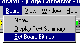
layout view. Once in layout view, use the Set Board Bitmap option as follows: This will attach the appropriate bitmap to the test file. |
 |
| How do I link
the components in the test list to the picture? After attaching a bitmap use Window Tile to display the test list and board picture together. Simply select a component in the test list then use the mouse to drag a box over the appropriate area on the picture. If you need to break the link right click the mouse over the selected component. Once you have done this for all components you can test simply by double clicking on the component you wish to test. On a FT100 you can select multiple tests by dragging the mouse over the group of components you wish to test. |
Polar Instruments Ltd polarinstruments.com Tel: +44 1481 253081 Fax: +44 1481 252476 © Polar Instruments 2002 |
 |
| © Polar Instruments 2002. Polar Instruments pursues a policy of continuous improvement. The specifications in this document may therefore be changed without notice. All trademarks recognised. | |