|
|
|
|
|
|
Testing impedance of differential pairs without ground
Application Note AP8153
|
|
|
This note, provided for historical information only, refers only to legacy equipment and methods and has been superseded by AP153 Background |
|
|
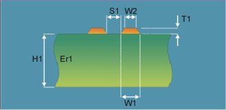
Consider the structure pictured alongside – an edge-coupled differential pair, minus the underlying ground plane. From a modelling standpoint the structure is like a paired wire transmission line. However the question arises – as this is a differential structure how should you test the impedance?
|
Edge-coupled differential pair without ground plane |
|
Modelling this structure The model above does not appear directly in the Polar field solvers Si8000m or Si9000e, however there is a simple adjustment you can make to one of the standard Si8000m or Si9000e structures to enable you to predict the finished impedance. |
|
|
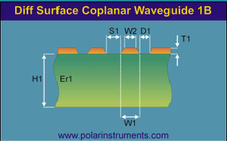
Select the "Differential Surface Coplanar Waveguide 1B" from the list of Si8/9000 structures (i.e. the structure without a lower ground plane) and set the ground strip separation dimension, D1, so it is 20 x that of the Trace Separation dimension, S1. This way the adjacent coplanar grounds will be far enough away to have negligible influence. Now you can model the above structure before putting it into production. |
Differential Surface Coplanar Waveguide |
|
Testing the structure In the structure to be tested all the signal current flows out through one conductor and the return current comes back through the other. With a signal of equal positive and negative going potential a virtual ground exists midway between the two traces. How do I connect probes to this? Imagine using a differential probe with + on one line and – on the other – you are left with nowhere to connect the ground. So in order to test you need to think of this structure as a single ended transmission line and consider connecting to it via a single ended probe. The signal goes to one side of the transmission line and the ground connects to the other. Using a single ended TDR and probe connection you can connect the probe either way around and measure the impedance of the structure using the system set for single ended measurements. The measurement returned will represent the differential impedance of the transmission line. For this structure this will equal Zo, the single-ended impedance. |
|
|
Footnote by Dr Alan Staniforth The impedance of the structure is the ratio of the voltage between, and the current in, the conductors. The concept of driving the conductors as a differential pair implies the presence of a zero voltage ground. The definition of the controlled impedance for this configuration does not require a ground. Hence, without loss of generality, one conductor can have zero voltage assigned to it. Thus only a single-ended measurement is required, even though one pin of the measurement probe is at ground potential. A three pin differential measurement probe requires a track configuration which already has a ground to which the ground pin is connected. A differential probe, in practice, measures the impedance between the two active pins and the ground pin. The differential impedance is calculated from these two impedances. If the ground pin is not connected, the impedance at the active pins will be incorrect and so will be the differential impedance. |
|