|
|
|
|
|
|
Enabling causal modeling in the Si9000e
Application Note AP8184
|
|
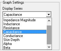
Si9000e frequency dependent calculations (Si9000e 2016 and later) For its frequency dependent calculations the Si9000e transmission line field solver provides you with the options of assuming fixed (i.e. frequency-independent) values for dielectric parameters or creating tables of values of dielectric constant and loss tangent at selected frequencies. The Si9000 graphs loss against frequency as well as other series, including impedance, capacitance and skin depth – simply select from the Graph Settings drop-down.
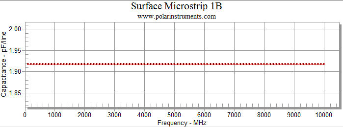
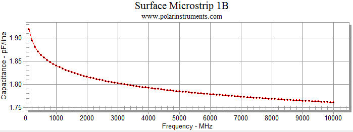
Using frequency independent capacitance modelling Choose a simple Surface Microstrip structure (i.e. a single substrate region); on the Frequency Dependent Calculation tab specify 100 frequency steps and from the drop-down choose (for this example) Capacitance and click Calculate – the graph of capacitance is shown below.
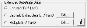
However, using frequency independent permittivity is a source of non-causal time domain responses. Causal interpolation of dielectric constant is implemented in the Si9000e lossy line field solver by employing the Extended Substrate Data options.
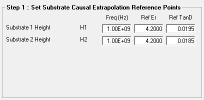
Applying frequency dependent modelling When faithful time-domain simulations are required (e.g. for high speed serial PCB links) accurate modelling is important. Modeling complex dielectric permittivity and loss tangent as fixed (i.e. frequency-independent) values leads to non-causal results. The Si9000e employs the Svensson-Djordjevic method for dielectric constant interpolation. The Svensson-Djordjevic model is a physically correct model of dielectric loss in the frequency domain that is well-behaved after transformation to the time domain. It works best when a single frequency is nominated for Er and the Svensson-Djordjevic interpolation calculates the appropriate Er vs frequency. Causally extrapolating substrate data Choose the Causally Extrapolate Er / TanD option from the Extended Substrate Data option group to apply Svensson-Djordjevic modelling to each dielectric layer in the current controlled impedance structure. The example below illustrates a controlled impedance structure with two dielectrics. The Causally Extrapolate Substrate Data dialog is displayed with an entry for each dielectric. Use the dialog to set substrate causal extrapolation reference points: values for frequency, Er and TanD.
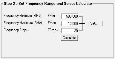
Set the frequency range and number of steps (or frequency increments.)
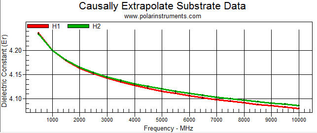
Click Calculate: the Si9000e charts Dielectric Constant (Er) v frequency for each dielectric.
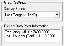
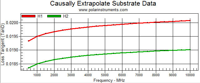
From the Graph Settings dropdown select Loss Tangent (TanD) to display the change in TanD over the selected frequency range.
Click a data point on the graph data series to display the value v frequency of the selected point.
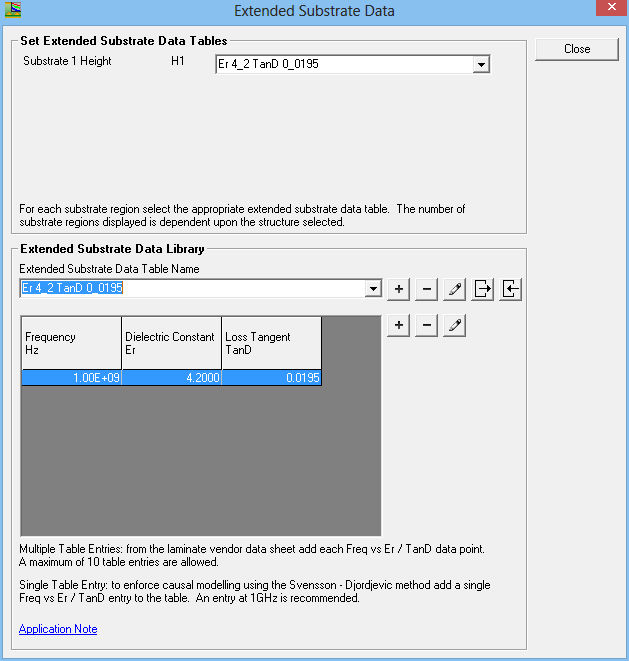
Multiple Er / TanD option Using the Multiple Er / TanD option the Si9000 can accept tables of multiple values of dielectric constant and loss tangent or use a single value to enable Svensson-Djordjevic frequency dependent permittivity modelling. When a single value table is used it employs the same modelling technique as implemented with the Causally Extrapolate Er / TanD option. To use the Svensson-Djordjevic method choose the Multiple Er / TanD option and click Edit to display the Extended Substrate Data dialog and add a single entry table. Click the Add New Table button, supply a descriptive name and add a single entry for Frequency, Er and TanD as shown in the example below. You will also need to specify your table in the Substrate Height drop-down.
Close the dialog and Calculate – the Si9000 implements causal modelling using the Svensson-Djordjevic dielectric loss model. Choose Capacitance – note the variation in capacitance with frequency. Compare with the frequency independent modelling above.
Note that the Si9000 applies frequency dependent permittivity modelling even though Er and TanD are specified with single values (i.e. as constants.) |