|
|
|
|
|
|
Single Frequency Loss Tangent Goal Seek
Application Note AP8193
|
|
Using the Si9000 Single Frequency Loss Tangent Goal Seek Measuring insertion loss yields the total losses of a transmission line, but sometimes it is useful to further process that information and deduce the contribution of copper losses and dielectric losses to the overall loss figure. Si9000e provides loss tangent goal seeking for both single frequency and multiple frequencies. This note describes single frequency loss tangent goal seeking. For multiple frequency loss tangent goal seeking see Application Note AP8207 The Si9000e simplifies the complexity of the process of estimating dielectric loss by allowing you to:
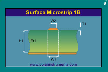
This figure can then be processed to provide a useful estimate of the dielectric loss tangent for the substrate material. Single and multiple-frequency loss tangent goal seeking Si9000e provides loss tangent goal seeking for both single frequency and multiple frequencies. This application note describes the sequence of steps to goal seek for loss tangent for a single frequency. Surface microstrip example Select Surface Microstrip 1B structure with the default parameters:
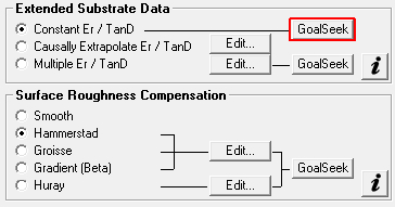
On the Lossless Calculation tab supply the structure parameters and calculate the impedance. Switch to the Frequency Dependent tab: Surface Roughness Compensation
Extended Substrate Data
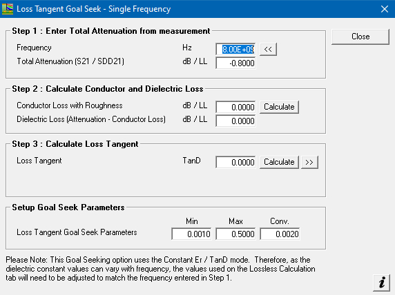
The Loss Tangent Goal Seek dialog is displayed.
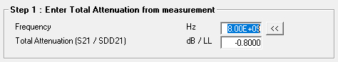
Step 1 – Enter the Total Attenuation Under Step 1 enter the Total Attenuation for the point of interest, the frequency and the loss per length of line –dB / LL. The length of line will be the value entered into the Length of Line (LL) parameter on the main frequency dependent tab, so could be a 1000 mils for dB/inch or 10mm for dB/cm.
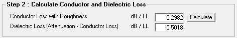
In the case of the Surface Microstrip 1B structure default for LL is 1000 mils so dB/inch. In this example the Total Attenuation at 8GHz = –0.8 dB/inch Step 2 – Calculate the Conductor and Dielectric Loss Under Step 2, Calculate the Conductor and Dielectric Loss. This will take the parameters for the current selected structure (Surface Microstrip 1B) and calculate the conductor loss at 8GHz. It will then take the calculated conductor loss from the total attenuation entered in Step 1 to calculate the remaining dielectric loss.
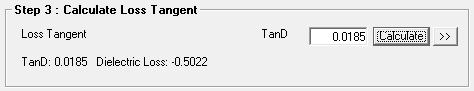
In this case the conductor loss is -0.2982 dB/inch so the remaining dielectric loss is -0.5018 dB/inch Step 3 Calculate Loss Tangent The Step 3 Calculate Loss Tangent option will allow the Si9 to calculate the Loss Tangent (TanD) required to achieve a dielectric loss of -0.5019 dB/inch. Using the Goal Seek Parameters to limit the min / max range of TanD the Si9 will now sweep the range of TanD values until a suitable TanD is calculated to achieve a dielectric loss of –0.5019 dB/inch. Notice the progress of the calculation is updated on the dialog.
The result is that the Loss Tangent (TanD) of 0.0185 is required to achieve a dielectric loss ~ –0.5018 dB/inch – the convergence value is used to give the target dielectric loss a tolerance. To verify, copy the TanD value of 0.0185 using the
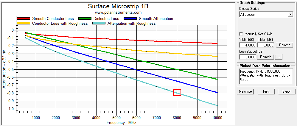
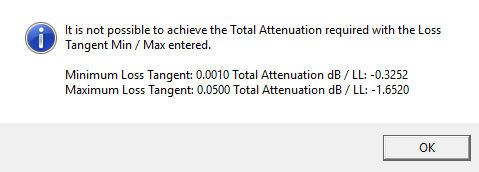
Query the Conductor Loss with Roughness, Dielectric Loss and Attenuation with Roughness curve data points at 8GHz – notice the Attenuation with Roughness (total attenuation) is now ~ 0.8 dB/inch as specified in the Goal Seek dialog. If the total attenuation value entered in Step 1 of the Loss Tangent Goal Seek option is unachievable the Si9000e displays the message alert below:
The minimum and maximum Loss Tangent values as specified in the Setup Goal Seek Parameters are displayed along with the calculated Total Attenuation. If you are not already using Si9000e v16.05 or above please contact your local Polar Sales Office for more information. |