|
|
|
|
|
|
Dielectric constant and loss tangent introduced
Application Note AP8198
|
|||
|
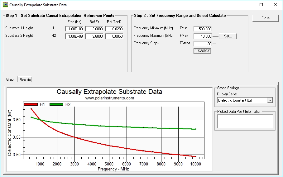
Are they related? Audience: – This note is for new PCB designers or PCB designers wanting to move into high speed design. It is intended to give a “feel” for the characteristics – more mathematical engineering discussions are widely available and can serve as follow on reading once you have a grasp of the concepts. This note explains in layman's terms how Dielectric constant and Loss tangent are related and the implications for PCB transmission line design. Think of a parallel plate capacitor. If the space between the plates is air or a vacuum the charge that may be stored between the plates is proportional to the area of the plates, inversely proportional to the spacing and proportional to the voltage. By introducing a non-conductive dielectric material between the plates the capacity for a given plate area is increased by a multiplier called the dielectric constant. So a larger dielectric constant permits more energy to be stored for a given plate area. Dielectric constant is a key material property and at low frequencies it is (usually) all you need to consider. However as frequency increases another property looms in importance. This is the loss tangent of the material. A good quality dielectric material for high frequency use will have a low loss tangent, a poorer quality material (though usually lower cost) will have a larger loss tangent. The dielectric loss is a result of the RF energy being converted to heat as the substrate charges and discharges and is proportional to the loss tangent and the frequency; the molecular and crystalline make up of the substrate has a significant impact on how much energy is consumed in this process. Low loss materials are designed with materials that dissipate minimum energy in the process of charging and discharging; as a packet of energy is turned into heat on each charge and discharge cycle the losses increase in line with the frequency of operation. Are the two properties related? A plot of Er for two substrates with an identical Er at 1GHz (3.6) but loss tangent of 0.02 (standard FR4) for one, and 0.005 (low loss) for the other shows the relationship:
Loss tangent plotted for a standard loss (red curve) and low loss (green) base material both with Er of 3.6 @ 1GHz (Polar Si9000e) What is happening? To understand the relationship you need to understand that the losses in a substrate are proportional to frequency, each time the substrate charges and discharges a tiny but measurable amount of energy is lost. At very low frequencies this is too small to notice, but as the frequency ramps up the losses in the substrate (heat) start to rob the dielectric of its ability to store energy. In the above example the low loss tangent dielectric has a much flatter Er curve (it always will). Note also that the Er of the high loss material is higher than the low loss at frequencies below 1GHz, this is because even at 1GHz the high loss material is already losing some of its energy storing capability. Some engineers are concerned (sometimes unnecessarily) about how transmission line impedance varies with frequency, and because the line impedance is the square root of (inductance per unit length divided by capacitance per unit length) they feel the impedance may vary significantly. It is worth considering that even on a relatively lossy material where Er falls a little more over frequency the impedance only varies a 1/ sq root Er, so it is a second order effect; this variation is mitigated further with lower loss substrates as the small value of loss tangent further flattens the Er curve over frequency. To explore how PCB transmission lines behave over a wide frequency range the Si9000e field solver (the source of the above graph) lets you explore the design space and model production variation and material choice of copper foil and surface treatment, PCB line width and height variation along with dielectric material modeling for a wide range of scenarios. More information on the Si9000e field solving PCB Transmission Line Design System. See also AP8194 Rounding loss tangent leads to large modeling errors |
|||