|
|
|
|
|
|
What is the highest frequency I can model with the Si9000e
Application Note AP8199
|
|||
|
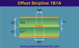
What is the highest frequency I can model with the Si9000e? (OR At what frequency does my structure stop being a transmission line?) Si9000e can accurately model transmission lines up to the onset of non-TEM (Transverse Electromagnetic) modes. Non-TEM modes will be set up if the propagating wavelength becomes a significant fraction of the physical dimensions of the conductor (e.g. conductor width and thickness.) TEM will be the only mode of propagation if the dimensions of a transmission line are electrically small – i.e. the dimensions are a small fraction of the wavelength of the highest frequency being transmitted. Strictly, at the onset of significant non-TEM modes the structure is no longer a transmission line, operating more like a waveguide, so you can think of this question as “At what frequency does my structure stop being a transmission line?" For the geometries in use this frequency is well above those encountered in high speed digital designs. So what is that frequency and what are the parameters that impact when a transmission line “ceases to be”...? The narrower the trace you are modeling the higher the maximum frequency it can operate at as a transmission line; striplines (i.e. in a uniform dielectric) are able to operate in this fashion at much higher frequencies than microstrips, where the signal propagates partly in the substrate and partly in air. Fortunately, with modern and shrinking geometries the cutoff frequencies are well above those normally encountered in high speed digital applications. Striplines
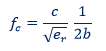
For a stripline the cutoff frequency for the lowest order non-TEM mode occurs at:*
Where fc is the cutoff frequency in Hz where the first non-TEM mode appears c is the speed of light er is the dielectric constant of the substrate b is the distance between planes For example, at 20 mil trace thickness and er of 4.3 the cutoff frequency is 141GHz ** Microstrips
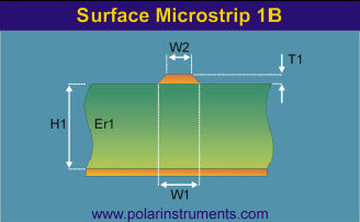
For microstrips there is no single cutoff frequency for non-TEM modes. The microstrip structure above is a mix of two differing dielectrics. Electromagnetic waves that propagate in a microstrip line exist in both air (above the trace) and the substrate (between trace and ground plane.) In microstrips signals of different frequencies travel at slightly different speeds; i.e. microstrips exhibit dispersion (a difference of delay for various parts of the signal.) Part of the signal propagates in TEM mode, part in other transmission modes. As a rule of thumb, to say in safe territory the thickness of the microstrip substrate should be limited to 10% of the shortest wavelength in use. For a more in depth discussion of the subject, consult the references below. * Advanced Engineering Electromagnetics Constantine A Balanis, John Wiley & Sons, 1989, ISBN 0-471-62194-3 ** High Speed Signal Propagation Howard Johnson and Martin Graham, Prentice Hall, 2003, ISBN 0-13-084408-X |
|||