|
|
|
|
|
|
Checking for resin starvation by using excess resin test in Speedstack
Application Note AP509
|
|
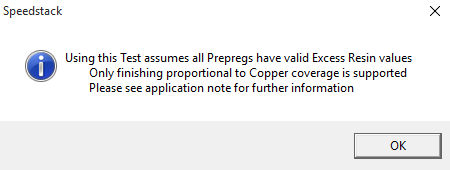
Using the Design Rules Check for excess resin (resin starvation test) Polar's Speedstack PCB Stackup Builder incorporates a comprehensive Design Rules Check (DRC) function that includes checks for symmetry, copper balance, minimum trace and gap widths and excess resin. Values for excess resin may be added to the material libraries for prepregs. This application note discusses how to calculate the excess resin value for the Polar Speedstack library field. If the excess resin test is specified Speedstack displays a warning dialog that all prepregs should have valid values assigned.
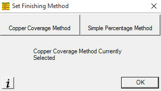
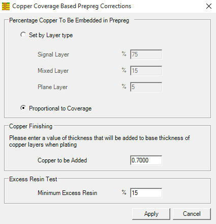
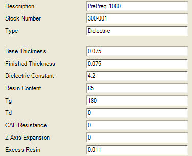
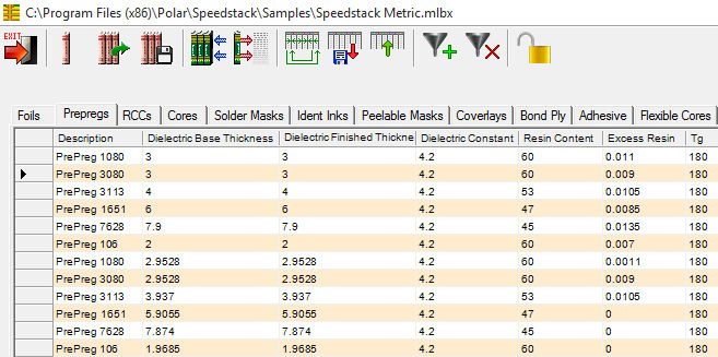
Calculating excess resin Note: The excess resin check is applicable when Speedstack is set up to use the Proportional to Coverage within the Copper Coverage method. The term "excess resin" is also known as a butter coat. A butter coat is defined as (IPC-T-50G) “An increased amount of resin on the outer surface of a base material”. Butter coating is frequently used to enhance the reliability of power PCBs Select Tools|Set Finishing Method|Copper Coverage Method. From the Copper Coverage Based Prepreg Corrections dialog choose Proportional to Coverage and specify the value for minimum excess resin. The resin starvation test is most reliable for values of copper distribution post-CAM between 10% and 90%. Speedstack's Excess Resin check is most useful as a guide to help the user to decide if there is sufficient resin within the prepreg regions to bond the opposing surfaces together, i.e. as an indication of potential resin starvation. The excess resin check is not a method to determine the minimum isolation distances between adjacent copper layers! Calculating excess resin example – Prepreg 1080 For this example consider a metric 1080 glass style. From IPC-4412A it is possible to obtain the glass style thickness without resin (See Appendix ii – Finished Fabric Glass Styles.) The data that is required is in the Thickness column; for our example, for a 1080 prepreg glass style, it is 0.053 mm or 53um. Given a value for the finished thickness of the prepreg in question (post-pressed thickness) you can easily arrive at a value for excess resin; for our example, take the finished thickness of 1080, which in the Speedstack sample library is equal to around 0.075mm (75um). From the finished thickness subtract the glass thickness. 0.075 – 0.053mm = 0.022mm (75um – 53um = 22um) This value is the total excess resin value. It is necessary to divide it by 2 to calculate the excess resin value per side; so for this example excess resin = 0.022mm/2 = 0.011mm (11um). Therefore, for this example, the excess resin for prepreg 1080 is 0.011mm (11um). Adding the excess resin values to the Speedstack library This value can be used to populate the library's prepreg Excess Resin field within Speedstack. Open the library to be edited (you may have to clear the current library). Click on the prepreg type to be modified to display the Review/Edit Prepregs dialog and supply the value for Excess Resin.
Repeat the process for all prepreg materials in the library (use the arrows to step through the material list). If appropriate, save the library.
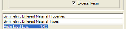
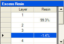
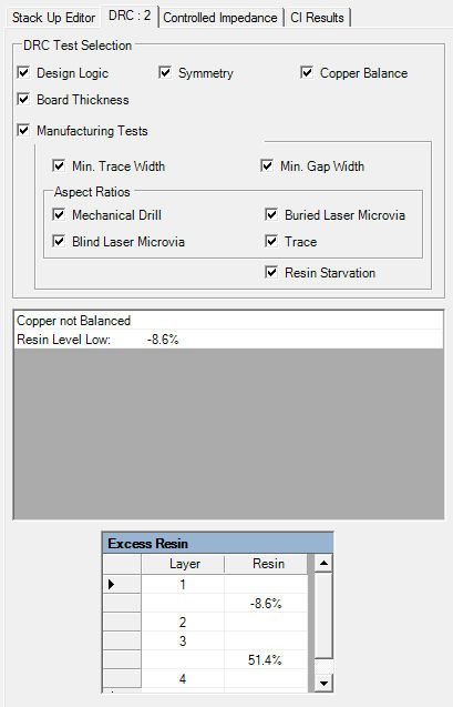
With values for excess resin specified for the prepregs used in the stack we can specify the Excess Resin test within the Speedstack's DRC. The DRC displays an error line containing the excess resin value for each faulty prepreg dielectric region along with a scrollable list of excess resin values for each prepreg region in the stack.
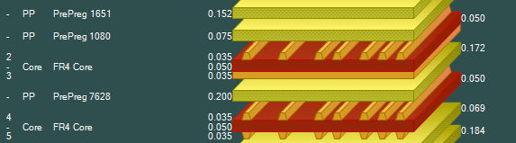
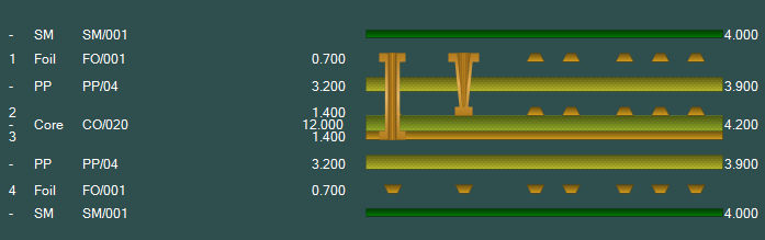
Clicking on the excess resin error line displays the faulty region in the stack. In the example below the error condition lies in the prepreg material between the two highlighted layers.
Calculating the Excess Resin DRC check percentages This section explains the formula that is used to calculate the Excess Resin DRC check percentages.
Example 1:
Example 2:
Where multiple prepreg layers exist between copper layers it is necessary to add the total excess resin for each prepreg material – step a. Where two copper layers are embedded into the same prepreg region it is necessary to add both copper layer embedded thicknesses – step b. For further information on this topic consult your base material supplier. |