|
|
|
|
|
|
Documenting differential pairs without underlying ground planes for Gigabit Ethernet routing in Speedstack
Application Note AP542
|
|||||
|
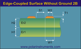
Documenting differential pairs without underlying ground A Speedstack customer recently asked how to document differential pairs without an underlying ground plane in Speedstack. Occasionally there are applications where a ground plane below the pair is undesirable (you can learn more about this via a search for Gigabit Ethernet application notes explaining how to route under and near Ethernet connectors.) This application note explains how to model and document this scenario in any situation where the differential pair needs to be a “pure” differential implementation. (100% of the signal and return being carried by the pair rather than partially returned through an underlying ground). The structure is depicted in the Si8000m and Si9000e field solvers in the graphic below.
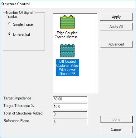
In Speedstack you need to be slightly creative to document this as the 2-D nature of Speedstack means you need to deploy a structure from a stackup with no apparent underlying ground. When you select a layer and use the structure selector to add a differential structure Speedstack displays it as shown in the following graphics (i.e. all the structures show ground below.) So how do you obtain a groundless structure in Speedstack? To reveal the available groundless structures you need to ensure that every reference layer in the stack is set to mixed signal / plane. Speedstack presents a list of applicable structures for the selected layer so the presence of a solid reference plane within the stack up will always result in a list of structures where a reference plane is present. Setting all reference layers to mixed signal / plane allows the structure selector to also provide access to structures without a separate reference plane, which is what Speedstack requires to model groundless differentials.
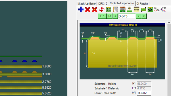
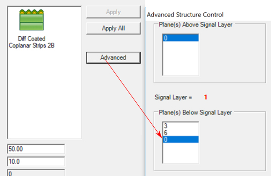
Click the Diff Coated Coplanar Strips With Lower Ground 2B and then click Advanced and set Planes Below Signal Layer at 0.
This will now allow you to enter groundless differential structures. In Speedstack they show as coplanar – and for modeling purposes simply set the space of the coplanar grounds to be far enough from the pair to be “out of harm’s way” – set to 10x trace width. Now you can insert the structure into your stack:
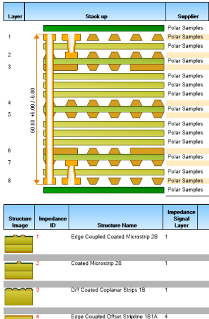
The structure will then appear in your finished Stackup printout as follows (shown above and in the report below as structure number 3.) From the File menu choose Print Technical Report to display the complete stack.
If you have questions about stackup documentation, impedance or insertion loss please contact your local Polar office. They will also be pleased to offer a Webex demonstration or evaluation license. |
|||||
 :
: