|
|
|
|
|
|
Using mini-stacks in Speedstack in rigid-flex constructions
Application Note AP544
|
|
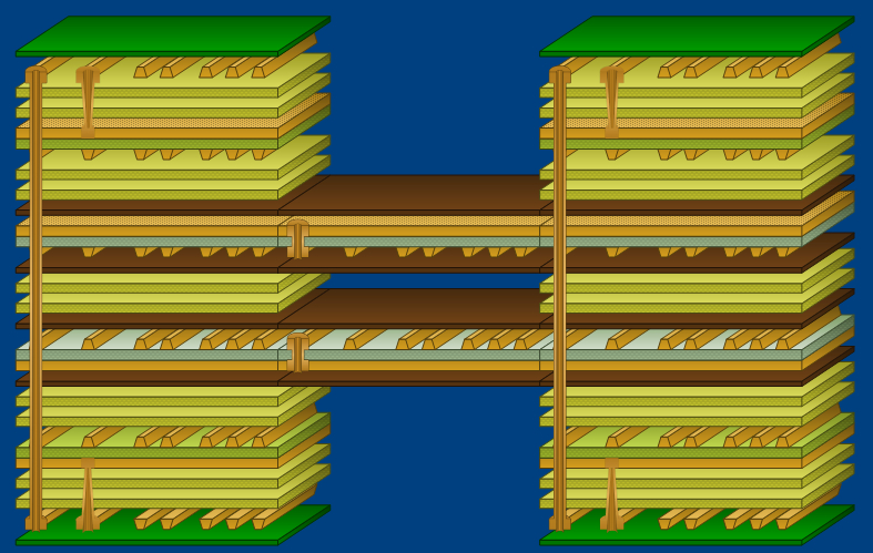
Creating and documenting flex-rigid stackups Speedstack Flex allows PCB fabricators and OEM engineers rapidly to create and document accurate and efficient flex-rigid PCB layer stackups. The Speedstack Flex Navigator enables the board designer to link and document as many cross sections as necessary in order to fully document a flex-rigid build up. Speedstack Flex supports documentation of common flex-rigid constructions, including doublets where stacked pairs of flex link two rigid sections of the flex-rigid construction together (see the graphic below.) Speedstack Navigator Speedstack’s Navigator works from a master stack comprising the full set of materials used in the final stackup and documents each rigid and flex-rigid section with as many "sub-stacks" as needed for the design. There are no limits to the number of sub-stacks or layer count of the total build. Consider the stack construction below, typical of a bookbinder flex, in which a stacked pair of flex sections link the two rigid sections of the flex-rigid construction.
When adding the first impedance structure to the flex sub-stack Speedstack allows the flex sub-stack to be specified as:
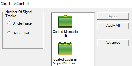
In many cases it would be appropriate to treat the individual stacks as mini-stacks from an impedance viewpoint but where the flex cross-sections would interact with each other the sub-stack can be defined as a single stackup with air between the flex sections as a dielectric. Adding controlled impedance structures When a controlled impedance structure is added to a signal layer, Speedstack displays the Structure Control dialog to allow the designer to choose a structure based on the arrangement of signal layers and reference planes. Click on the sub-stack to display it in Speedstack's Stackup Editor.
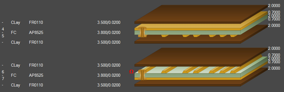
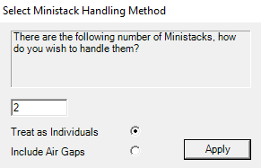
The flex sub-stack above can be regarded as a single stack with an air gap between two flexible layers or as two separate stacks (ministacks) If a controlled impedance structure is added (in this case to signal layer 6 in the sub-stack above) the flex sub-stack above must be defined either as a single stack with an air gap or two separate "ministacks". When the first structure is added Speedstack displays the Select Ministack Handling Method dialog
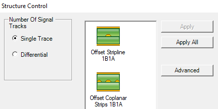
The mini-stack handling method chosen will determine the structures available for the selected layer. The structure options are shown in the dialogs below. Defining the sub-stack as a single stack with air gap
Defining the sub-stack as two ministacks
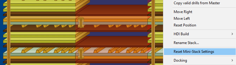
Sub-stack impedance structure options For the sub-stack above specified as a single stack with an airgap, structures on layer 6 will effectively be offset striplines or offset coplanar strips. If the sub-stack is defined as two mini-stacks, impedance structures will function as coated microstrips or coated coplanar strips. Resetting mini-stack settings The current mini-stack settings for the flex sub-stack may be reset from a single stack to two mini-stacks and vice versa. Note: – resetting the stack handling method clears the structures on the sub-stack. Select the flex sub-stack in the Speedstack Navigator (shown highlighted in red below.)
Right click the sub-stack in the Speedstack Navigator and choose Reset Mini-Stack Settings – the controlled impedance structures added to the sub-stack will be cleared from the sub-stack. When a structure is next added to the sub-stack Speedstack displays the Select Ministack Handling Method.
As described earlier, redefine the sub-stack as a single stack with airgaps or two separate stacks. Any new structures added to the sub-stack will reflect the chosen mini-stack handling method. |