|
|
|
|
|
|
Using separate design files per sub-stack to support etched off copper layers and changes with copper finished thickness
Application Note AP562
|
|
|
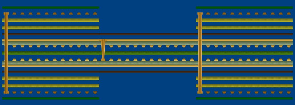
Speedstack Navigator works with shared materials between sub-stacks and that works for ~95% of rigid-flex constructions. Sharing materials between the sub-stacks has great advantages, editing the properties or swapping a shared material in any of the sub-stacks immediately updates the other sub-stack(s), so significantly speeds the creating and editing of rigid-flex constructions.
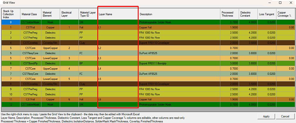
However, for some designs it might be necessary to etch off the copper layer from the flex core or change the copper finished thickness for the same electrical layer in one sub-stack only. If this is what you need, use Speedstack to build each sub-stack as a separate stackup file and use the Layer Name property (displayed to the right of the stack up) to maintain linkage between the sub-stack common copper electrical layers. Start with the rigid sub-stack (the Master stack) that contains all the electrical layers and assign the Layer Name that will be common to all sub-stacks. Use Grid View to assign Layer Names quickly to all electrical layers rather than selecting the Properties for each material.
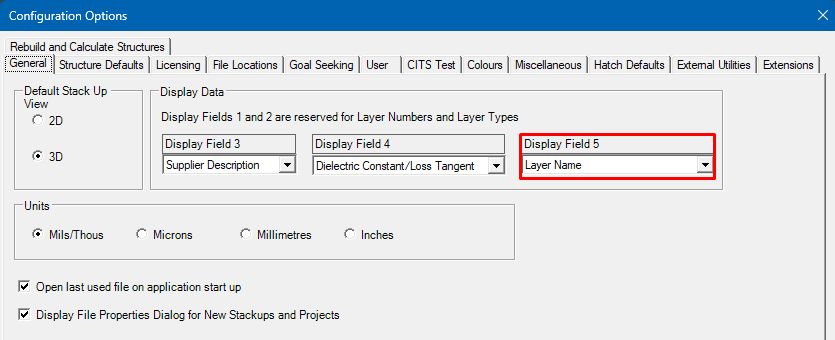
To display the layer designation alongside each layer, from the Tools|Options|Configuration Options, choose Layer Name in Display Field 5
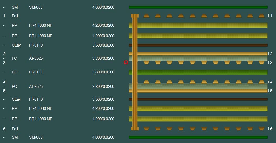
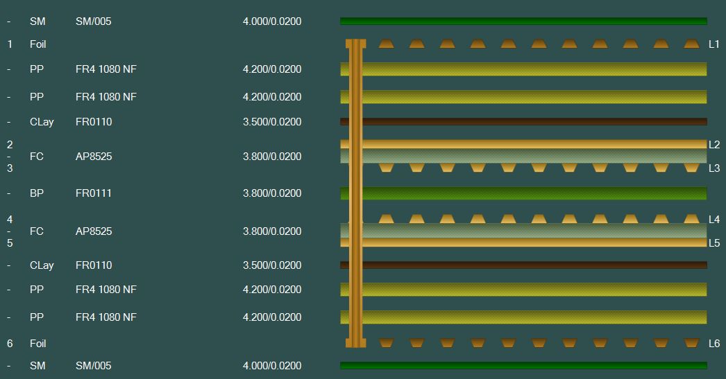
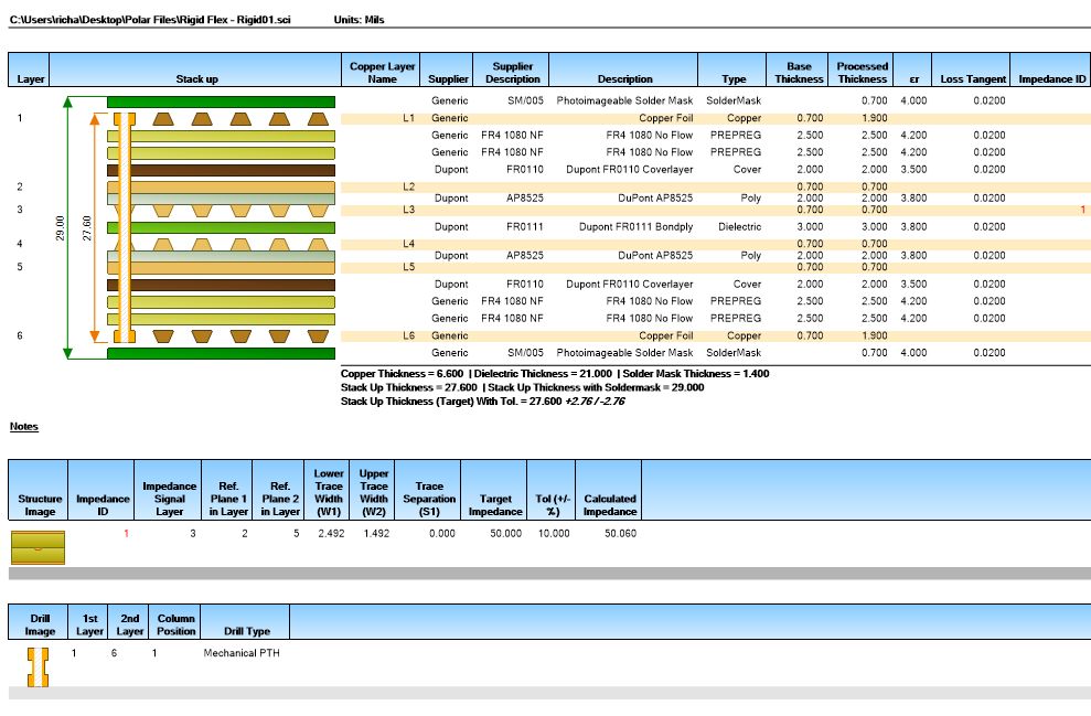
Save the rigid sub-stack – in this example, ‘Rigid Flex – Rigid01.SCI’ * – shown below
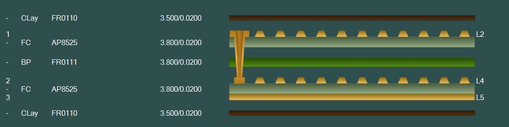
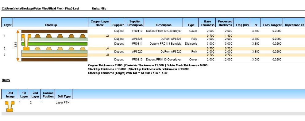
Remove the materials from ‘Rigid Flex – Rigid01.SCI ’that are not required for the flex sub-stack, add any materials that are unique to the flex sub-stack, amend the copper thicknesses and use the Core / Flex Core Properties | Remove Copper option to remove the etched away copper surface that exists in the flex sub-stack only. Notice how the L2 / L3 core on the Rigid sub-stacks is double-sided, but now it's possible to have L3 etched away on the Flex. In addition, the copper thickness on L2 on the Flex is 1.4 mils (or any other different value) rather than 0.7 mils on the rigid sub-stacks Save as ‘Rigid Flex – Flex01.Sci’ * – shown below.
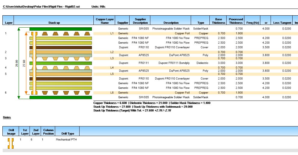
Decide which of the two existing sub-stack files is closest in terms of requirements to the third sub-stack. In this example, the third sub-stack closely resembles ‘Rigid Flex – Rigid01.SCI’ so open this file and make the necessary changes. Save as ‘Rigid Flex – Rigid02.SCI’ * – shown below.
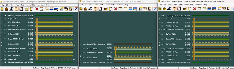
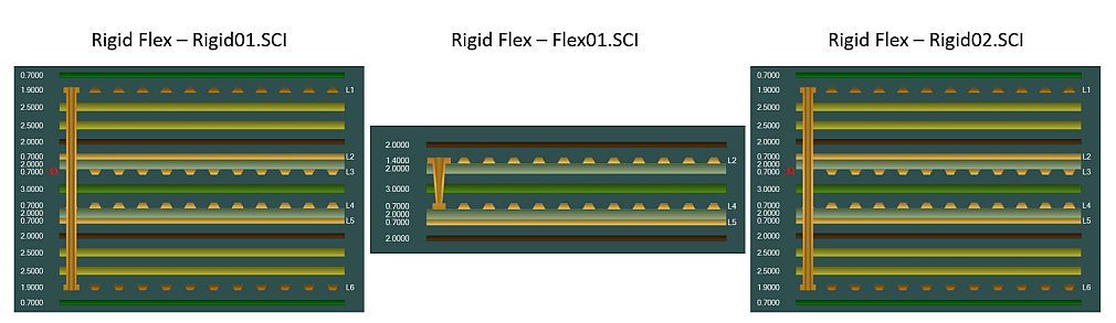
By using separate Speedstack files, each sub-stack can be independently edited The three instances of Speedstack (each containing a separate sub-stack file) can be displayed side by side as shown below.
The instances of Speedstack can be shifted vertically so that the layer numbers (in this case, L2, L4, L5) can be aligned.
The stackups are reflected in their respective Technical reports. The first rigid (Master) stack – project file Rigid Flex - Rigid01.sci:
The flexible stack – project file Rigid Flex - Flex01.sci:
The second rigid stack – project file Rigid Flex - Rigid02.sci:
In conclusion – Speedstack Flex caters for well over 95% of rigid flex stackups “out of the box” but for a small number of specialised builds, especially those where copper is fully etched away on some substacks or has thickness in flex areas that varies from the rigid part of the stack, then the precise documentation is best achieved by documenting each sub stack individually with its own .sci file rather than the Speedstack Navigator. * The project files discussed in this application note are available for download and experimentation. |
|