|
|
|
|
|
|
Potential sources of measurement error whilst testing impedance
Application Note AP130
|
|||
|
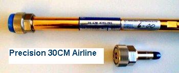
Measuring Impedance When measuring impedance with a Polar CITS or any other TDR there are a number of sources of potential measurement error. This application note sets out to explain those error sources and how you can minimise them in order to achieve repeatable and accurate measurements Which probe I should choose for most accurate measurements? The best first choice is the IP50, as the best measurements are made where only one impedance change occurs between TDR and test coupon. The only exception is where you are measuring short traces and here you should read Application Note AP127 Measuring short traces when using a TDR which deals with this subject in detail. Calibration TDRs used for impedance measurement are precision RF measurement tools and need to be regularly calibrated. Reference air line standards are used for TDR calibration and are available in a variety of standard impedances. Precision air lines are a high cost item and an acceptable alternative for less critical applications is a set of precision semi rigid cables calibrated against air lines.
Air lines are made traceable by a precision metrology technique called air gauging which allows the internal bore of the air line to be measured and the impedance calculated using a standard formula. Hands OFF! Resting your hand or fingers on a test coupon will cause the impedance of surface structures to drop. Ensure operators are aware of this effect. It's easy to demonstrate, simply make multiple tests on a surface trace and see how placing your fingers on the board surface alters the measurement.
Secrets of TDR Calibration Here is some information previously only known by TDR specialists – a TDR's calibration will only be correct if it is calibrated with the same DC conditions at the end of the test cable as those occurring when you measure. Simply stated, if you calibrate a TDR using a precision broadband resistor as a standard you should also terminate your test sample (coupon) with the same resistance. However, if you calibrate your TDR with an open circuit standard such as an air line you should measure your test sample without resistive termination. As it is inconvenient to fit a terminating resistor to a test coupon always calibrate a TDR used for coupon testing with an air line. The error between the two methods can be as much as 3 or 4 ohms. The reason for this effect is that TDR sampling heads are precision fast switching diode bridges and are sensitive to temperature change. A change in DC conditions at the test sample will alter the DC output voltage of the pulser. Worn Cables and probes. RF Cables and probes have a finite life and should be regarded as consumable, with 24 / 7 operation they will intime become resistive and ultimately fail. Cable life can be extended by careful handling, no tight bends etc. Avoid falling into the trap of one PCB fabricator whose well meaning operator intentionally used worn probes to help a batch of boards pass that were out of spec! Polar RITS automated impedance test systems incorporates software and on board calibration systems that detect cable and probe wear and alert operators of maintenance requirements Drift All TDRs are susceptible to measurement drift over time and with temperature range. Ask if your TDR makes compensation automatically for this? If you use a Polar CITS or RITS internal stable standards are incorporated and the units recalibrate at regular intervals. For best performance check your config and options are set to recalibrate every 10 minutes. A RITS has two settings, one calibration setting for internal calibration and a second setting for checking for probe wear (airline calibrate.) This second setting should be set to 60 minutes for optimum results. Are mobile phones influencing your measurement? Mobile phones are RF transmitters, they regularly "sign on" to the nearest base station – even when you are not making a call.
Test coupons are around the same length as a mobile antenna and themselves will receive the signal from your phone. This is especially the case with surface structures like microstrip. Ensure phones are switched off in the test area. Even the work surface? Yes, even the work surface can influence measurement results. The work surface has its own dielectric constant and a microstrip on the bottom of the test coupon or PCB will measure low if it is too close to the table surface. Two ways to resolve this – place the coupon in a test fixture or support jig. Or turn the coupon over so the bottom layer faces up. Test coupons provide a reliable way of verifying PCB impedance, and will offer you more reliable repeatable measurements than attempting to measure the board itself. The advantages of using test coupons are described in detail in Application Note AP124 Testing with Coupons. Important note: If your striplines are reading high - did you remember to short the planes Vcc and Gnd on the coupon? (NOT on the board!) Vcc and grounds need to be shorted on the coupon especially on narrow coupons to simulate actual RF conditions on the finished board. Tip: If increasing the height of the top plane to 10 x its normal height on the CITS25 gives you a reading of impedance similar to your measured value you have probably not shorted the planes on the coupon. |
|||