|
|
|
|
|
|
GRS500 CADView – PCB paperless repair with multi-format CAD viewer
- Version 2016 now available
|
|
|
|
|
|
GRS500 CADView multi-format CAD viewer includes over 30 popular CAD formats GRS500 CADView enables you to test and fault-find assembled PCBs using CAD data Saves hours searching through schematic diagrams View over 30 popular CAD formats |
|
|
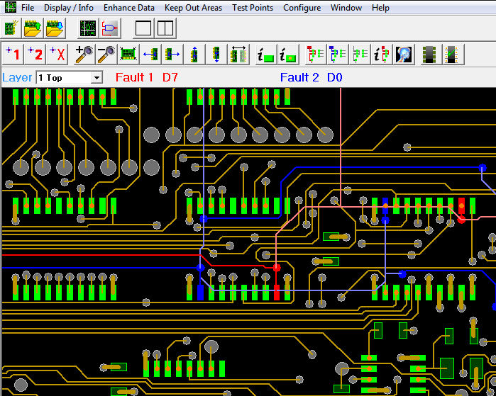
Paperless repair Imagine a facility to selectively X-ray a faulty net. Even more important is the ability to use the GRS PCB repair facility to highlight faulty nets on screen — even when they disappear into an internal layer. |
|
|
|
|
|
Highlight faulty nets Flip and mirror data so you can work on both sides of the circuit board Use the graphical interface to help you trace faults without reference to paper schematics.
Supports the following CAD formats: Input processor list:
|
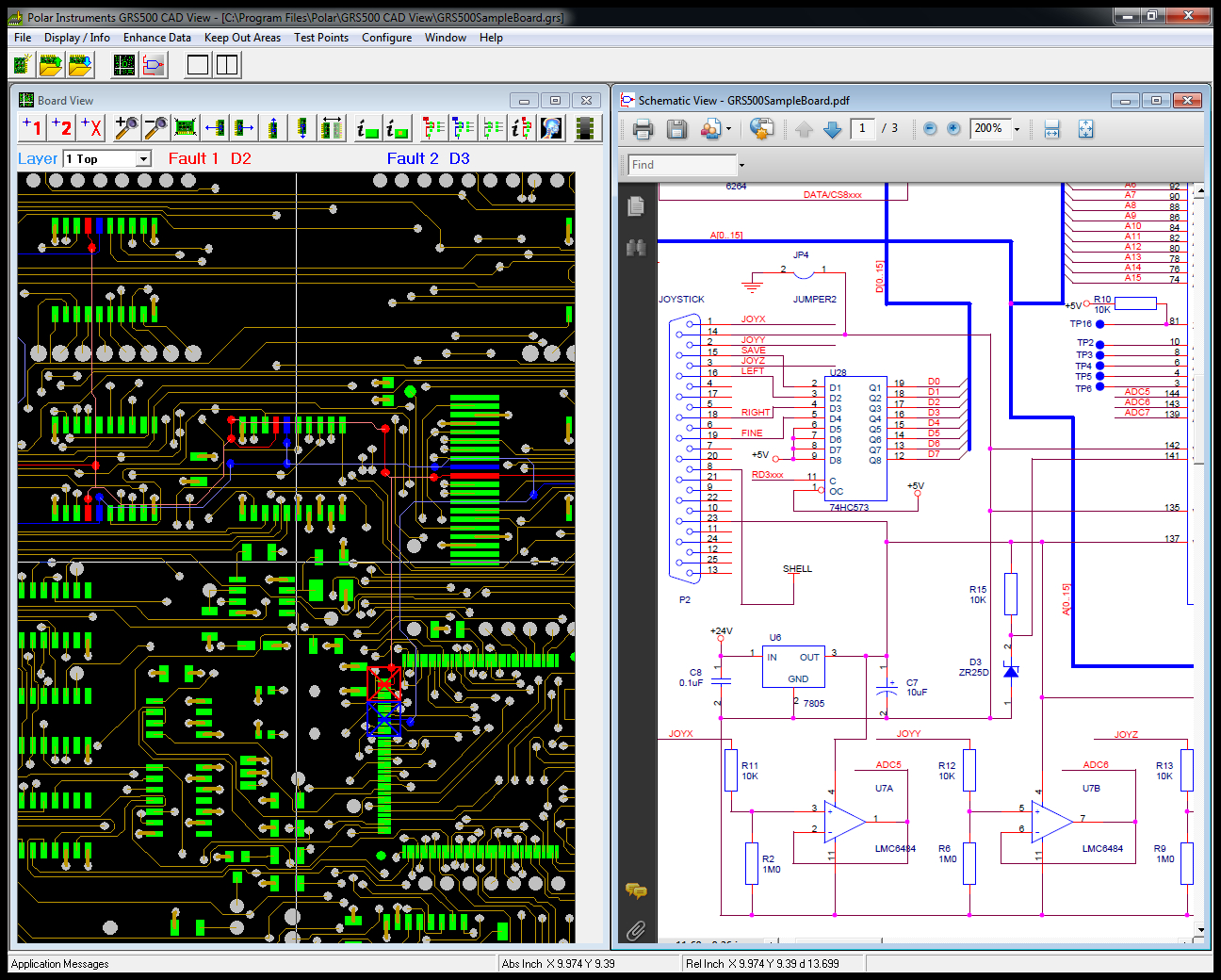
Virtual “X-ray” One of the most useful and Powerful features of the GRS500 CADView is its ability to selectively display fault data. This is best seen in the Virtual X-ray facility where the faulty net is displayed both on the main layer view and in a ghosted image as it traces through other layers. Only the fault information is displayed as it traces through inner layers, and this makes it easy for technicians to trace a faulty net as it disappears and re emerges from inner layers. Display and fault entry. Faulty nets can be selected with a mouse click or by entering net name directly. The net immediately highlights in red or blue. You can query net information on each faulty net, and also select the amount of information on display – it's easy to add or suppress pad net and other display information so that all you have to focus on is the process of troubleshooting. For instance, when you turn over a board to investigate faults on the rear it is a simple operation to mirror the data in X or Y so you can continue to trace the faulty net. Support for most popular CAD formats Powerful yet easy to use Polar GRS500 CADView enables you to import over 30 popular CAD formats and display the CAD data in an easy to use environment that is optimized for PCB troubleshooting. Suitable for raw or assembled boards the GRS500 is able to import both CAD and CAM formats, including OrCad, PADS, IPC D356, Cadstar, Mentor and many others. Link to Schematics If your CAD system supports Adobe .pdf format schematics, you can simply click on any of the displayed nets and be transferred to the relevant point on the schematic diagram – invaluable when you are faced with a board containing many high pin count devices. **Gerber data is photo-plotting information and contains limited data for repair purposes. Polar recommends you choose to use CAD data wherever possible. How do I import my CAD files and which files do I need? Which CAD input processors are supported? AP207 Gives you all the information you require. |
|
Polar GRS500 CADView works with Adobe Reader™ XI |
|