|
|
|
|
|
|
Track Resistance Calculator TRC Plus – calculating the resistance of printed circuit board tracks
Application Note AP144
|
|
|
Note: This application note refers to the Polar Track Resistance Calculator (TRC Plus.) Earlier versions of the Track Resistance Calculator (TRC) are described in Application Note AP144b. Calculating the resistance of printed circuit board tracks It is sometimes necessary to know the DC resistance of a track, for example, for power supply applications or when there is a need to work on fine geometries and take series loss into account. The resistance of the track is a function of the resistivity of the track material and the length and cross section area of the track and can be calculated as discussed below. Polar's Track Resistance Calculator (TRC Plus) is available as an option for the Si8000 and Si9000.
Resistivity is the extent to which a material opposes the flow of electric current if it is cast into the cross sectional area of a side and flows perpendicularly Resistance (R) is directly proportional to the length of conductor and inversely proportional to area of the cross section through which the current is flowing. To a first order calculation: Resistance = Resistivity × Length / Cross Sectional Area i.e: R = ρ × L / A Rearranging: ρ = R × A / L Its SI unit is Ohm metre However, resistivity is not constant but varies with change in temperature; therefore temperature and the Temperature Coefficient of Resistance (TCR) should be taken into account. The resistance of a track can then be expressed by: R = (ρ * L / A) * (1 + α * (T – Tref)) where: When calculating track resistance the Polar Track Resistance Calculator (TRC Plus) assumes that the Resistivity, Reference Temperature and TCR are values known by the user when entering new materials. Use the Tools|Calculate TCR command to calculate TCR if the two temperature and resistivity values are known Calculating TCR In order to calculate the TCR, the following are needed: From this we can calculate the Temperature Coefficient of Resistance Temperature Coefficient of Resistance = Change in Resistivity / Original Resistivity × Change in Temperature i.e. TCR = (ρ2 – ρ1) / (ρ1) × (T2 – T1) Once we have the TCR we can find the new resistivity values at different temperatures. New Resistivity = Original Resistivity x (TCR x (Change in Temperature) + 1) i.e. ρ2 = ρ1 (α (T2 – T1) + 1) Voltage Drop (VD) Once the track resistance is calculated, calculating the voltage and current that would flow through it is straight forward. VD = Current x Resistance Adjusting Rho to suit the measurement units you use Confusion, terror and error often arise because some conversion of the MKS value for ρ is required to cope with the variety of units which are normally used in industry. Nobody measures track dimensions and areas in metres. In Metric units, microns (sometimes called micrometres with the symbol μm or mm) are more common for cross section dimensions. Track length is more normally in centimeters or millimeters (cm or mm) In American units, even more confusion reigns when converting to thousandths of an inch (old name "mil", now the IPC standard is "thou" or "thousandth") for the cross section, and inches for the length. Knowing that one metre is approximately 39.37 inches, you can derive a value of ρ which takes into account the units of your choice. See next. Typical adjusted values for Rho ρ You may find the following values of ρ to be useful in calculating resistance of tracks and connections. For copper:
For gold:
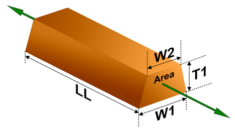
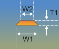
Cross Section Area (A) The typical cross sectional profile of an etched track is trapezoidal, illustrated by the figure. The cross sectional area, A, of a trapezoid is found from the equation A = 0.5*(W1 + W2)*T1
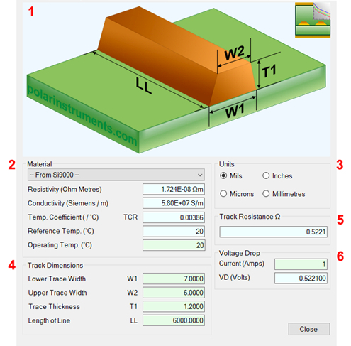
Figure 1 However, the formula R =ρL/A holds whatever the cross sectional shape. You simply have to calculate A for that shape. Making the calculation easy The TRC Plus dialog box can read in the current structure values from the field solver or allow entry of material type, track shape and length; the Track Resistance Calculator returns a result in Ohms for the specified trace. TRC Plus considers temperatures and Temperature Coefficient of Resistance. The sections of the dialog are described below.
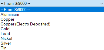
1. Interactive track material image. Clicking on a track parameter label will highlight the associated Track Dimension field (text box). Enter data into the active field. Double-clicking anywhere on the image will bring up the Materials Editor. 2. Material selection and properties Select the material via the drop-down list.
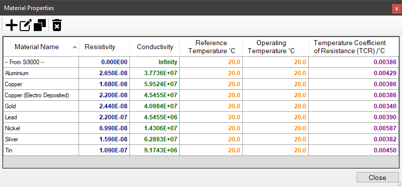
Fields coloured in light-blue are not directly editable but the field values can be in the Materials Editor. Fields coloured in light-green are editable by the user. For example, Operating Temperature will determine a material’s resistivity at that temperature, which in turn will be applied in calculating the track resistance. 3. Units Switch to your preferred units by clicking the associated option button – imperial units include Mils (Thou) and Inches; for metric units choose Microns (Micrometres) or Millimetres. 4. Track or trace dimensions Enter or change track dimensions in the Track Dimensions in the chosen units. 5. Resistance result Calculation of the track resistance. The result should update immediately upon any changes to the editable (light-green) fields. 6. Voltage Drop calculation result The calculated Voltage Drop is displayed in the VD (Volts) text box. Using the Material Properties Editor The Material Properties Editor is the source of the list of materials found in the drop-down list, above, on the main application window. Click Tools|Edit Materials to open the Material Properties Editor.
Use the Toolbar buttons to add, edit, duplicate and delete materials as needed.
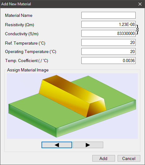
Adding new materials Click the Add Material button to open the Add New Material dialog.
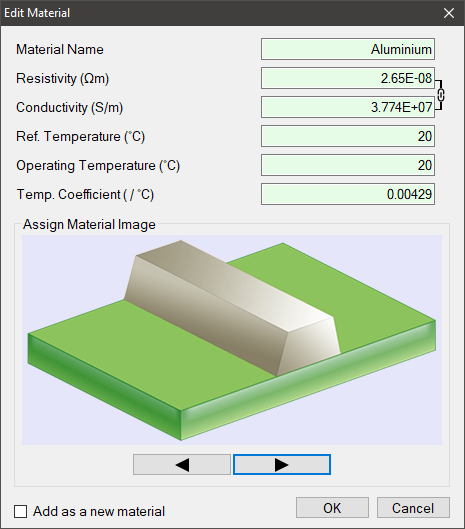
Supply the material name and the values for other parameters in their associated fields; note that the Resistivity and Conductivity fields are interactively linked. Step through the range of material images and choose an image to assign to the new material; click Add – the material will appear in the material properties list. Editing materials Select a material and click Edit to modify the material parameters: the Edit Materials dialog is displayed.
Change the values in the parameter text boxes to reflect the material values and click OK. Click the Add as new material checkbox to add the modified material as a new material. Duplicating materials Materials currently in the list can serve as "templates" for new materials. Select an existing material and click the Duplicate button – the material is copied to the list: the duplicated material can then be edited to reflect the new description and values. Deleting materials Use the Delete Selected Material button to remove a material from the list. |