|
|
|
|
|
|
An introduction to forward and reverse
crosstalk
Application Note AP8164
|
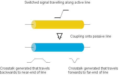
What is crosstalk? Crosstalk is the unwanted coupling of energy between two or more adjacent lines. This unwanted coupling can change the required signal. Crosstalk size estimations are commonly divided into two separation calculations (See Fig. 1.)
Fig 1 Overview of crosstalk induced noise If the victim line is not terminated at both ends in its characteristic impedance the induced spurious signals can reflect at the ends of the line and travel in the opposite direction down the line. Thus a reflected near-end crosstalk can end up appearing at the far end — and vice versa. Scope The crosstalk figures discussed in this note are the peak values as calculated by popular and frequently quoted formulae for maximum ease of comparison. These equations only hold when coupling is weak and the following assumptions apply:
Near-end crosstalk The magnitude of the near-end crosstalk is dependent upon the mutual capacitance and inductance between the two interacting lines and it will increase to a maximum amplitude as the coupling length increases. Assuming two identical lines:
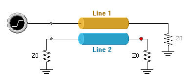
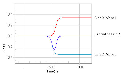
The figure, Kb, which shows the maximum near-end crosstalk is a dimensionless ratio of voltages between the victim and aggressor lines. Far-end crosstalk The far-end crosstalk can be considered as an effect caused by the difference in velocity between the odd and even modes of propagation and thus a difference in edge arrival times at the end of the line — see Figures 2 and 3 below.
Fig 2
Fig 3 Far-end crosstalk caused by the superposition of even and odd mode waveforms The far-end crosstalk coupling coefficient (Kf) can be calculated by:
This can be written as:
The far-end crosstalk coupling coefficient (FEXT) is a unitless ratio of the maximum voltage perturbation caused on the victim line.
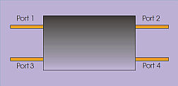
Far-end crosstalk increases with a sharper risetime, a longer coupling length and a higher Kf factor. In an ideal homogeneous stripline situation there will be no far-end crosstalk. Summary The electromagnetic fields between two closely coupled lines interact with each other and will affect the behaviour of the signals on both lines. The formulas given here will enable the maximum peak effect to be predicted. Appendix: Frequency Dependent Crosstalk For a more complete solution to the crosstalk effect, the s-parameters should be examined. S- parameters define how a single frequency sine wave interacts with a “black box” device and affects the output signal appearing at different output ports. Crosstalk is the output on a port of a line different from the applied signal. Using the “modern” s-parameter port numbering scheme, a signal is injected
at port 1, the return loss is S11 and the transmitted signal is S21.
Thus the near-end crosstalk is represented by S31, and the far-end crosstalk is represented by S41. Crosstalk parameters from different geometric models and materials can be directly compared to determine their respective merits and identify trends. Note: The Polar CITS series controlled impedance test systems displays crosstalk (XTalk) as a percentage value; the Si9 displays NEXT and FEXT as voltage values normalised to 1 volt. The Si9 value therefore needs to be multiplied by 100 to get the CITS number. Note that NEXT and FEXT are shown in the Si9000 with values of opposite polarity. See also: AP157 Even mode and common mode characteristic impedance, Zoe, Zcm, Zo, Zdiff AP174 Proximity effect of a ground plane on an electric field Further reading: If you would like more information on signal integrity issues, click the link below for a brief list of Polar Instruments recommended study material: |