|
Graph sensitivity
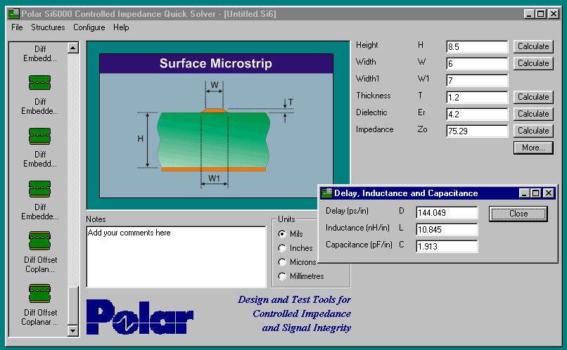
Quick Solver
Click picture for full screen
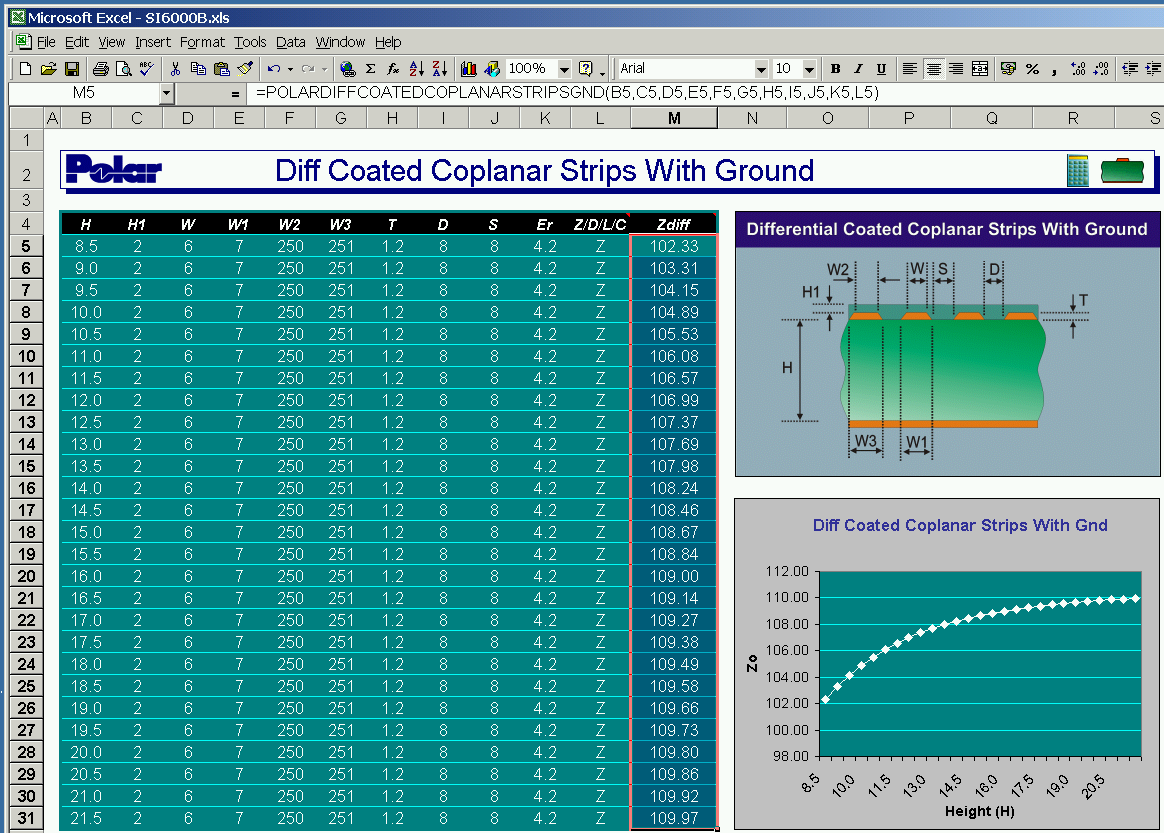
Now paste directly from Quick solver
into Excel
|
Si6000c  Powerful
impedance design system Powerful
impedance design system
 Impedance Goal seeking Impedance Goal seeking
 Increase
yields Increase
yields
 Reduce time to market Reduce time to market
Graph production variations
Single ended and
differential impedance
Odd mode Zoo, even mode Zoe,
common mode Zcm
Si6000c
Field solving Impedance
design system
The Field Solvers in the
Si6000 allow you to accurately graph impedance against various PCB
parameters. The Si6000 controlled impedance design system is a
comprehensive controlled impedance design aid which can run stand alone as
a Quicksolver, or the underlying engine can be applied directly though a
Microsoft Excel user interface.
|
The Si6000 allows you to produce impedance controlled boards with maximum yields.
You can also use the Si6000 to reduce the number of prototype iterations
before production ramp up. How?
You have 3 powerful methods of using the field solvers. One:
A quick solving calculator lets you seek a target impedance by varying any
one parameter, it could be line width, stack height or Er; you choose the
variable and set the goal seek you can even set realistic targets for
your own production limits. Use the Edit / Copy to Excel to take values
from the Quick solver and paste directly into the Si6000 Excel
spreadsheet Two:
A package of Microsoft® Excel spreadsheets allows direct access to the field
solvers;
you can graph any parameter you choose using the pre-prepared Microsoft
Excel
workbooks. Three:
Si6000 Expert mode allows you to access the Polar field solvers directly
through Microsoft Excel and build them into your own workbooks. This lets you feed
production data back into the field solvers so you can close the loop on
your process control. |
| With the ever increasing speeds of modern circuitry
the demand for high quality controlled impedance printed circuit boards is
continuing to grow. Today's PCBs are not just simple electrical
interconnection devices, they are complex highly specified components in
their own right. As the demand for controlled impedance PCBs has risen
there has been a subsequent increase in requirement to verify these board
designs prior to manufacture.
Differential Impedance PCB Structures
Coplanar Impedance Structures
Single Ended Impedance Modeling
Microstrip and Stripline Constructions
Field Solving by Green's function and
Method of Moments
Windows 95/98 and Windows NT / Windows 2000 Operation
The Si6000b field solving
impedance design system offers advanced field solving methods to model most circuit
designs and is totally complementary to the CITS500s and RITS520a manual
and automatic Controlled Impedance Test Systems. CITS measurement systems have been in
use with leading PCB manufactures throughout the world since 1991 and
Polar is recognised as a world leader in production line impedance
testing. Polar's innovative product portfolio includes the Toneohm 950
short circuit locator which is able to pinpoint the physical
location of shorts between maximum copper layers. |
| Support
Please take a look at the
controlled impedance application note pages you will gain maximum benefit
from your Si6000 if you read these supporting notes. These brief
articles help you
translate the precision output of the field solvers into practical real
world PCBs with good production yields.
|
| Constructions |
| Single-Ended |
Surface Microstrip
Coated Surface
Microstrip
Embedded Microstrip
Symmetric Stripline
Offset
(Asymmetric) Stripline |
| Differential |
Surface Edge Coupled Microstrip
Coated Edge
Coupled Microstrip
Embedded Edge Coupled Microstrip
Symmetric Edge
Coupled Stripline
Offset Edge Coupled Stripline
Symmetric Broadside
Coupled Stripline |
| Coplanar |
Surface Coplanar waveguide
Surface Coplanar strips
Coated Coplanar waveguide
Coated Coplanar strips
Coplanar waveguide
Embedded Coplanar waveguide
Embedded Coplanar strips
Offset Coplanar Stripline
All above structures with or without ground plane |
Differential
Coplanar
|
Surface Coplanar waveguide
Surface Coplanar strips
Coated Coplanar waveguide
Coated Coplanar strips
Embedded Coplanar waveguide
Embedded Coplanar strips
Offset Coplanar Stripline
All above structures with or without ground plane |
| Si6000 extracts |
Single ended and
differential impedance
Zo
Zdiff
Zoo
Zoe
Zcm
L/unit,
C/unit,
Tpd
|
| System
requirements |
|
|
Computer
|
IBM
PC compatible
|
|
Processor
|
1GHz
Pentium minimum 2GHz+ recommended
|
|
Operating
system
|
Microsoft
Windows 95, Windows 98, Windows ME
Microsoft Windows NT, Windows 2000, Windows XP
|
|
System
memory
|
256MB
minimum recommended
|
|
Hard
disk space required
|
100MB
(min.)
|
|
Video
standard
|
SVGA
(1024 x 768 min.)
|
|
CDROM
drive
|
|
|
Mouse
|
Microsoft
compatible
|
|
Spreadsheet
|
Microsoft
Excel 2000 or later
|
|
Software Activation
|
Parallel port hardware
key or
USB key
For floating licenses please refer to Si8000m
|
|
For multiple dielectric
support please refer to the new Si8000m
|
|
| Download a demonstration |
|
| Need more information?
Ken Taylor is your
Signal Integrity Product Manager
|
ken.taylor@polarinstruments.com
|
| Copyright© Polar
Instruments 2003. All trademarks recognised. |