|
|
|
|
|
|
PCB Controlled Impedance Field Solver for single and multiple dielectric PCBs
|
|||||||||||||||||||||||
|
|
|||||||||||||||||||||||
|
Si8000m – importing and charting logged data from CITS – comparing modeled with measured impedance Can't view the video? Click here |
|||||||||||||||||||||||
|
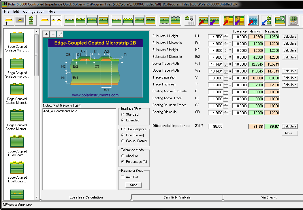
Si8000m PCB Controlled Impedance Field Solver – for single and multiple dielectric PCBs The Si8000m is a boundary element method field solver that builds on the familiar easy to use user interface in earlier Polar impedance design systems. The Si8000m adds enhanced modelling to predict the finished impedance of multiple dielectric PCB builds and also takes into account the local variations in dielectric constant on close spaced differential structures. The Si8000m assumes negligible insertion loss in the transmission line; should you wish to model insertion loss the Si9000e adds extensive insertion loss modeling capabilities The Si8000m links with Speedstack as Speedstack PCB. Si8000m options
|
|||||||||||||||||||||||
|
What's new in the Si8000m?
|
||||||||||||||||||||||
|
Si8000m features
|
||||||||||||||||||||||
Si8000m – comprehensive modeling of over 100 structures Surface coating is often overlooked when modelling and the Si8000m models the resist thickness adjacent to above and between surface traces. This offers a much more elegant solution which can be tailored to the particular resist application method in use on your boards. The new Si8000m also extracts even and common mode impedance. (Even mode impedance is defined as the characteristic impedance of one side of a transmission line pair when both lines are driven by a signal of equal magnitude and polarity). It is becoming increasingly necessary to control these characteristics on high speed systems such as USB2.0 and LVDS. |
|||||||||||||||||||||||
|
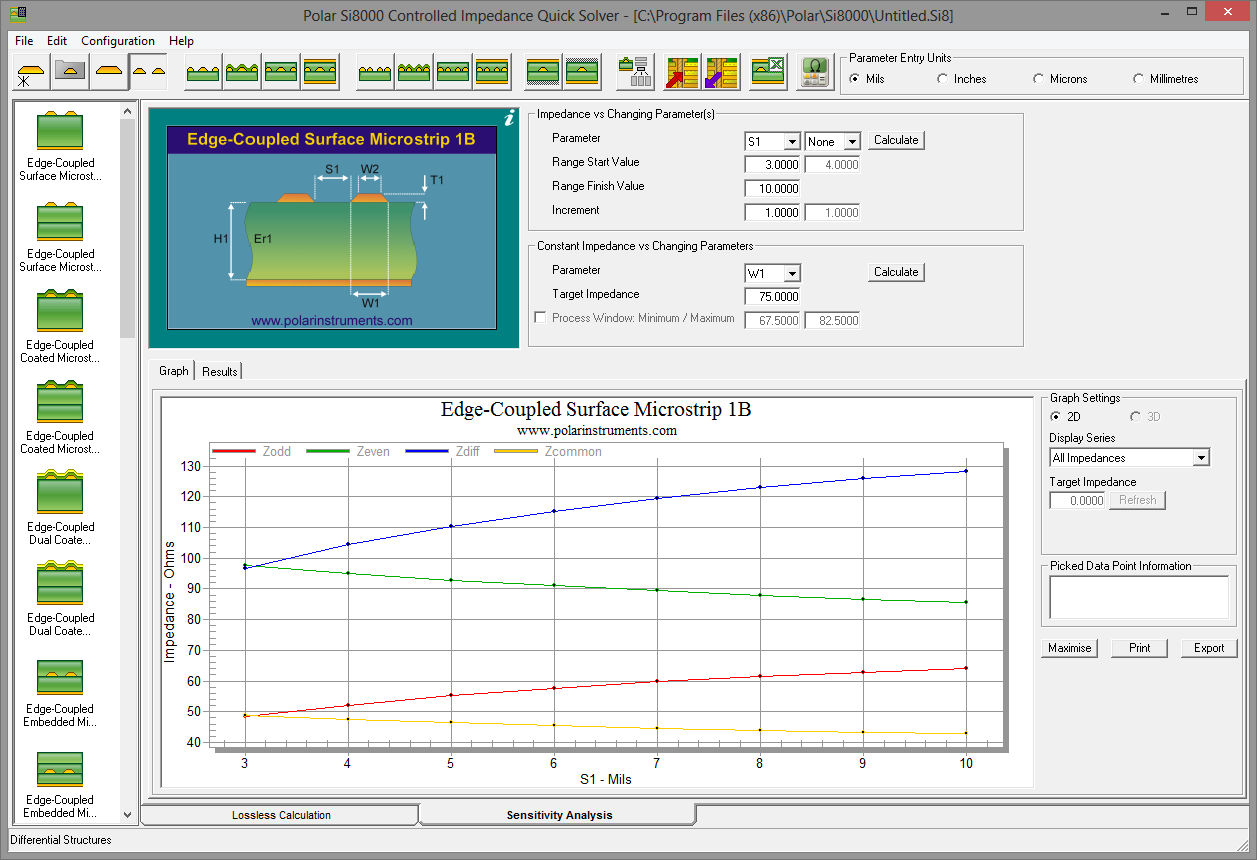
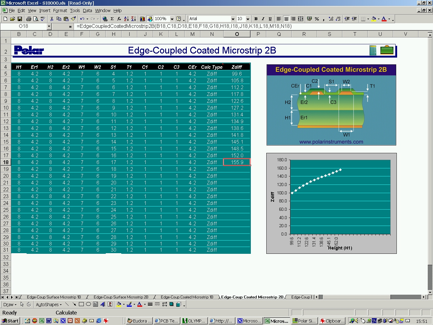
Field solving Impedance design system The Field Solvers in the Si8000m allow you accurately to graph impedance against various PCB parameters. The Si8000m Controlled Impedance Design System is a comprehensive controlled impedance design aid which can run stand alone as a Quicksolver, or the underlying engine can be applied directly though the optional Microsoft Excel user interface. The Si8000m allows you to produce impedance controlled boards with maximum yields. You can also use the Si8000 to reduce the number of prototype iterations before production ramp up. How? You have 2 powerful methods of using the field solvers. One: A quick solving calculator lets you seek a target impedance by varying any one parameter, it could be line width, stack height or Er; you choose the variable and set the goal seek – you can even set realistic targets for your own production limits. Use the Edit / Copy to Excel to take values from the Quick solver and paste directly into the Si8000m Excel spreadsheet Two: With the Si Excel option, a package of Microsoft® Excel spreadsheets allows direct access to the field solvers; you can graph any parameter you choose using the pre-prepared Microsoft Excel workbooks or build your own workbooks to model your process. |
|||||||||||||||||||||||
|
With the ever increasing speeds of modern circuitry the demand for high quality controlled impedance printed circuit boards is continuing to grow. Today's PCBs are not just simple electrical interconnection devices, they are complex highly specified components in their own right. As the demand for controlled impedance PCBs has risen there has been a subsequent increase in requirement to verify these board designs prior to manufacture.
The Si8000m field solving impedance design system offers advanced field solving methods to model most circuit designs and is totally complementary to the CITS500s and RITS520a manual and automatic Controlled Impedance Test Systems. CITS measurement systems have been in use with leading PCB manufactures throughout the world since 1991 and Polar is recognised as a world leader in production line impedance testing. Polar's innovative product portfolio includes the Toneohm 950 short circuit locator which is able to pinpoint the physical location of shorts between maximum copper layers. Monte Carlo impedance analysis – predicting production spread of trace impedance For designers and board fabricators wishing to predict the outcome of the board manufacturing process Monte Carlo impedance analysis in Si8000m and Si9000e makes light work of simulating impedance variation in a production run of PCBs.
Support Please take a look at the controlled impedance Application Notes – you will gain maximum benefit from your Si8000m if you read these supporting notes. These brief articles help you translate the precision output of the field solvers into practical real world PCBs with good production yields. Ask us about support packages for your Si8000m. Si8000m language packs Contact polarcare@polarinstruments.com for local language information |
|||||||||||||||||||||||
|
|||||||||||||||||||||||