|
|
|
|
|
|
Si9000e PCB field solver extracts insertion loss, RLGC and s-parameters
|
|||||||||||||
|
|
|||||||||||||
|
View video – compare Si9000e modeled insertion loss with VNA measurement Can't view the video? Click here |
|||||||||||||
|
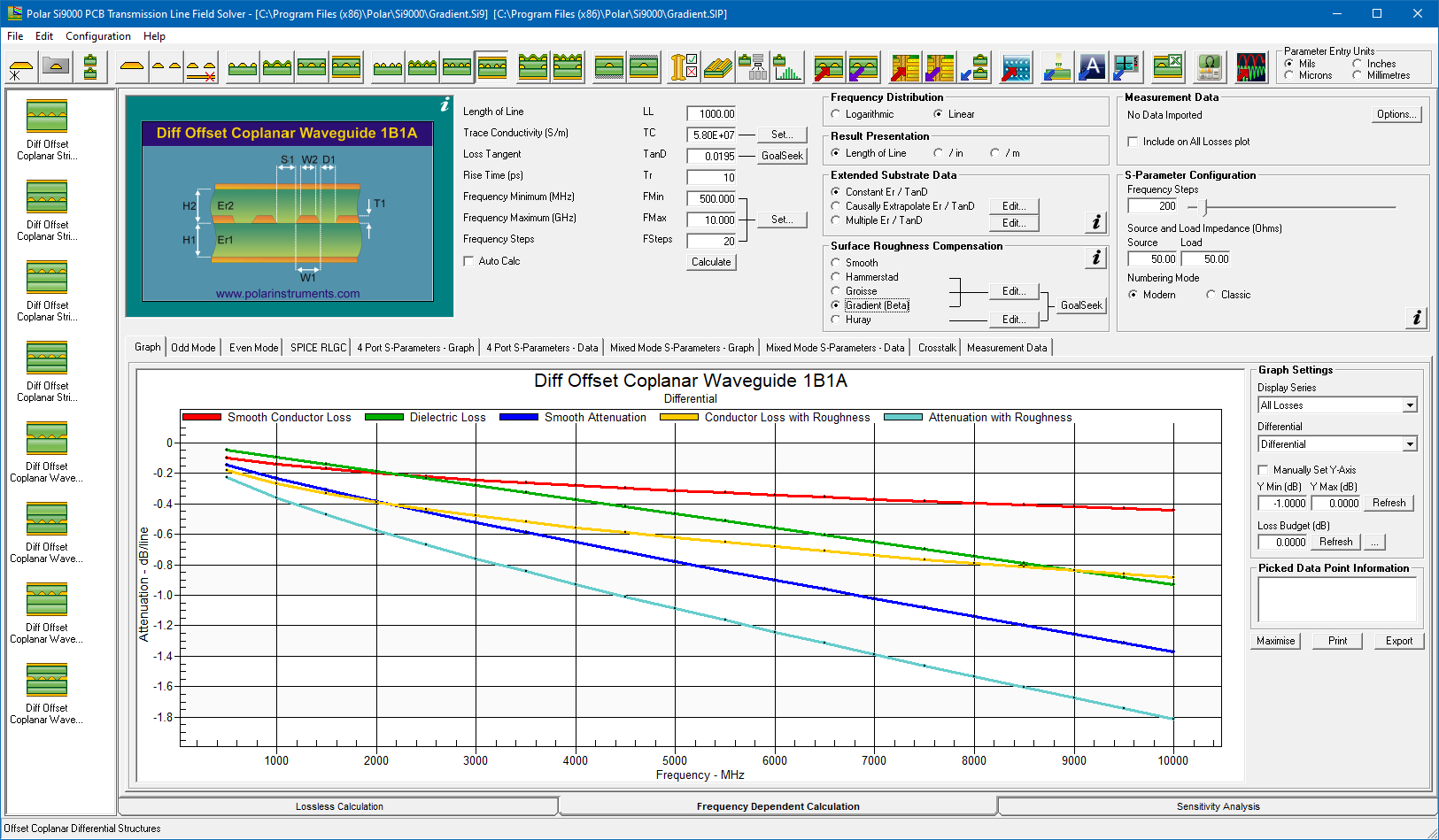
Si9000e fast accurate PCB transmission line modeling. With its fast, accurate, frequency-dependent transmission line modeling, the Si9000e Insertion Loss Field Solver is designed to model transmission line loss, impedance at given frequencies and extract full transmission line parameters over a wide range of popular PCB transmission lines (over 100 structures). Employing boundary element method field solving, the Si9000e extracts RLGC matrices and rapidly plots a range of transmission line information for the structure you are designing. Loss is graphed three ways with clear indication of dielectric, copper and total loss and includes Huray / Canonball /Gradient plus legacy Hammerstad, & Groisse methods for roughness modeling:
Si9000e graphs all losses – conductor, dielectric and insertion loss. The Si9000e caters for both single and multiple dielectric builds and comes with the ability to take into account solder mask performance. Mask coverage can be set adjacent, between and above traces. Many Polar customers request frequency-dependent impedance modelling, with particular reference to transmission line losses – the result is the Si9000e. The Si9000e is built on the same proven boundary element field solving platform as the PCB fabrication industry standard Si8000m. Increasing numbers of engineers are using the Si8000m as a rapid and accurate design tool for transmission line impedance – the Si9000e extends the output to extract full transmission line parameters. |
|||||||||||||
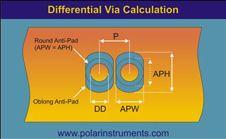
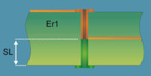
Differential Via Calculation / Via Stub Check The Si9000 incorporates: Differential Via Calculation, providing a quick and accurate circuit model for modelling differential through-hole vias. Via Stub Check that provides the signal distortion effect of a via stub. The effects of the stub will increase as the stub length and Er increase and the signal rise time reduces. The Si9000e Via Stub Check supports three modes:
Differential Via Calculation Polar Application Note AP8204.pdf (Design Note from Bert Simonovich) introduces a simple and practical methodology that provides rapid, accurate circuit modelling of differential through-hole vias. Via Stub Check Polar Application Note AP8166 (Vias, stubs and minimizing their visibility to high speed signals) explains how to check if, at your desired bit rate or operating frequency, you need to take steps to reduce or remove the effects of via stubs. |
|||||||||||||
|
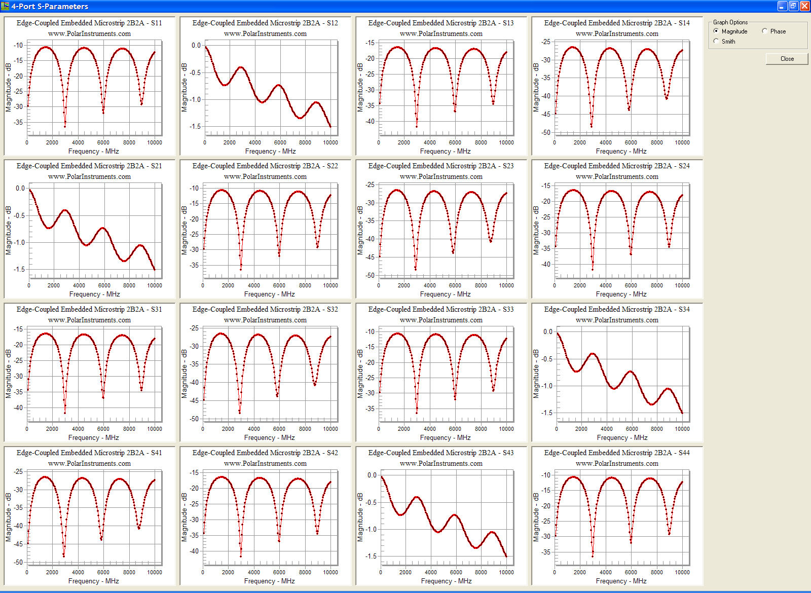
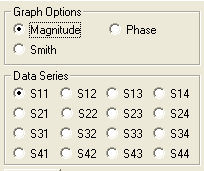
Powerful S-parameter graphing With the Si9000e PCB Insertion Loss Field Solver you can view the full range of 2 and 4-port S-parameters in a single chart window.
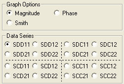
Click on the links below to display the full range of 4-port S-parameters data series, S11 – S44. Mixed mode The Si9000e provides a comprehensive range of data presentation in both tabular and chart form with the option of single-ended and mixed-mode S-parameters.
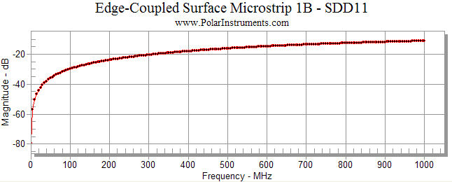
The differential S-parameters, SDD11, for an edge-coupled surface microstrip are shown below.
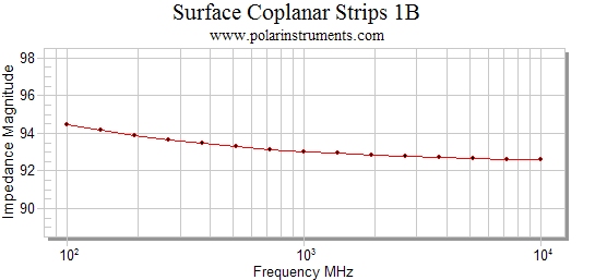
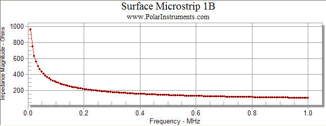
Frequency-dependent calculations Employing its Boundary Element Method field solving, the Si9000e extracts RLGC matrices and 2-Port (single-ended) or 4-Port (differential) S-Parameters and rapidly plots transmission line information for the structure under design. Graphing against frequency is provided for impedance magnitude, loss (conductor loss, dielectric loss and insertion loss), inductance, capacitance, resistance, conductance and skin depth. The Polar Si9000e runs within the Microsoft Windows environment and provides for simple transfer of table data to external programs such as spreadsheets or databases for subsequent analysis. Si9000e graphs Impedance v Frequency
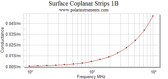
Impedance magnitude with frequency Conductance v Frequency
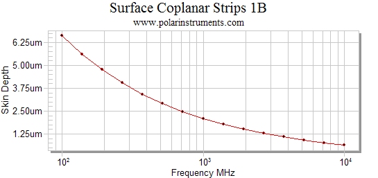
Conductance v frequency Skin depth v Frequency
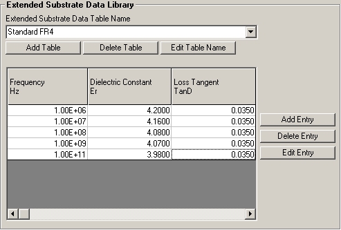
Skin depth v frequency Extended substrate tables The Si9000e frequency-dependent calculations can be refined using extended substrate data. Assign substrate values by frequency band to accommodate material from manufacturers who specify parameters that vary by frequency. Manufacturers may specify, for example, differing values of Er and loss tangent across a range of frequencies.
Extended substrate data tables Frequency dependent calculation range For frequency dependent calculations the Si9000e calculation engine supports lower frequencies down to 1KHz.
|
|||||||||||||
|
High layer-count builds For those working with complex high layer-count builds the Si9000e also links to the Polar Speedstack PCB Stackup Design System and is available in the Speedstack Si package. Using the Speedstack Si allows you to keep all your stack design data in one convenient file – and you can draw library material from your fabricator or from base material suppliers in the Polar Material Partner program. Designed to save you time compared with traditional methods, the Si9000e lets you choose graphically the structure you need to model and enter the geometric and material data and the range of frequencies under analysis. Select the graphs or table you need and the Si9000e solves for the results. Advanced users may also enter available data for Er and TanD versus frequency – the Si9000e will take these into account. |
|||||||||||||
|
|||||||||||||